
Emergency power systems are only as reliable as the last test that genuinely stressed them. A generator that starts and carries a light building load every month can still collapse when a transfer switch slams the full emergency load on in a single step, or when a genuine fault drags voltage down for 200 milliseconds. That gap between "it runs" and "it performs" is exactly what fault-rated load banks are built to close.
This paper ranks seven emergency simulation load bank platforms by how well they support power fault testing — not just steady-state kW dissipation, but controlled step loading, low-voltage ride-through simulation, unbalanced and leading-power-factor conditions, and verifiable transient data. The ranking reflects capability breadth, typical rating envelope, and how useful each platform is during commissioning, periodic exercising, and post-incident investigation.
What "Rated for Power Fault Testing" Actually Means
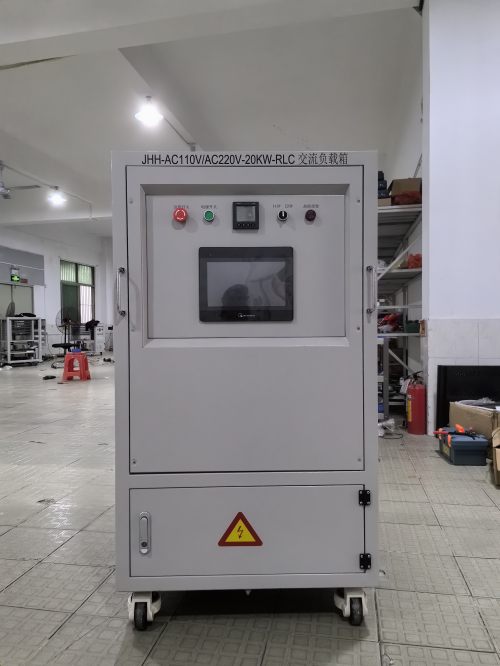
A load bank is a controllable sink. It converts electrical energy into heat and, in reactive versions, exchanges reactive power with the source under test. It does not generate fault current — that comes from the source, a sag generator, or a series reactor. What separates a fault-capable bank from an ordinary resistive heater bank is three things:
- Transient authority. Fine step resolution (typically 5–25 kW on a multi-megawatt bank), fast and repeatable switching (SCR or vacuum/contactor arrays), and the ability to apply or dump a large block in well under one second without arcing or contact welding.
- Controlled disturbance capability. The ability to hold a programmed load profile while the source voltage, frequency, or phase angle is deliberately disturbed — sags, swells, phase jumps, two-phase faults, harmonics — and to keep sinking power through the disturbance without tripping on its own protection.
- Withstand and coordination. Short-time current withstand, correctly rated cables and terminations, and protective devices coordinated with the system under test so that the bank never becomes the weakest link or masks a real coordination problem.
Ratings must be read carefully. A bank sold as "2,500 kVA" at 0.8 power factor delivers 2,000 kW of real power; a resistive-only bank of the same kVA number cannot reach rated alternator current at rated power factor at all. Voltage tolerance, ambient derating (often 1% capacity per °C above 40 °C), altitude derating, and duty cycle all change what the nameplate actually means on site.
The Seven Platforms
1. Containerized Resistive Load Banks — 480–600 V, 500 kW to 3 MW
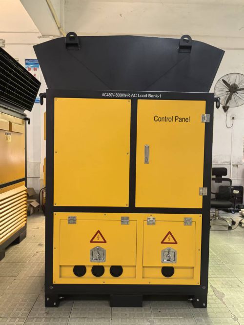
The workhorse of emergency power acceptance. A single ISO container houses forced-air resistive elements, a step controller, and a local HMI, delivering 5–25 kW resolution up to full rating. This is the platform that satisfies periodic exercising regimes such as NFPA 110 monthly runs and annual load tests, and it is the fastest route to proving that a diesel genset accepts a block load equal to its nameplate in one step without exceeding the allowable voltage and frequency deviation.
Fault-test role: block load acceptance, step-load profiling, sustained rated-load endurance, and governor/AVR recovery-time measurement. Watch-outs: resistive-only designs cannot verify an alternator at rated kVA and 0.8 PF; specify a reactive companion unit if that test is in scope.
2. Medium-Voltage Resistive-Reactive Banks — 2.4–13.8 kV, 5–50 MVA
Once the system under test is a medium-voltage generator, paralleling gear, or a utility-fed emergency bus, the bank must be able to present a lagging power factor. Inductive steps let commissioning engineers load an alternator to its full kVA rating at 0.8 PF, which is the only way to expose excitation ceiling limits, AVR instability, and reactive-sharing errors between paralleled machines.
Fault-test role: excitation and AVR response, reactive load sharing, circulating current between paralleled gensets, and verification of protection settings under realistic load angle. Watch-outs: MV banks need proper switching, grounding, and arc-flash boundaries; the interconnecting cable capacitance alone can dominate the reactive balance on short runs.
3. Leading-Power-Factor and Capacitive Banks for UPS and Transfer Systems
Modern double-conversion UPS systems must be validated with leading power factor loads, because capacitive loading stresses the inverter output filter and can drive instability that never appears with resistive loads. Capacitive step banks, often combined with resistive sections in a single enclosure, reproduce the 0.9 leading condition typical in data center specifications.
Fault-test role: inverter stability at leading PF, transfer-switch testing under load, break-before-make timing verification, and downstream breaker coordination during transfer. Watch-outs: capacitive steps create switching transients and resonance with source inductance; step sizing and dv/dt limits matter more here than on any resistive bank.
4. Voltage-Sag and Fault-Ride-Through Simulator Banks (LVRT/HVRT)
This is the platform most directly tied to the word "fault." A programmable sag generator — transformer-tap or impedance-based — creates the dip, phase jump, or unbalanced condition, while a fast load bank provides the real-power burden that keeps the source operating at a realistic operating point. Together they let a site reproduce a 0.5 pu three-phase sag lasting 150 ms, a single-phase-to-ground fault, or a repetitive flicker profile without touching the utility.
Fault-test role: ride-through verification for inverter-based emergency sources, protective relay coordination, undervoltage trip threshold validation, and post-fault recovery behavior of ATS and UPS controls. Watch-outs: confirm the bank can hold load through the sag without its own undervoltage protection dropping it out — this is the single most common specification gap.
5. Combined Electrical and Thermal Load Banks for Mission-Critical Facilities
Hospitals, data centers, and laboratories need more than electrical proof: the cooling plant must survive the same event. Combined banks pair resistive electrical loading with ducted heater sections or heat-recovery elements, so UPS output and chilled-water capacity are stressed simultaneously at design IT load. The result is a genuine integrated systems test rather than two disconnected commissioning activities.
Fault-test role: end-to-end validation of the electrical and thermal path during a simulated outage, including cooling recovery time after transfer and the behavior of economizer and staging controls. Watch-outs: heat rejection must be planned before the container arrives; ducted designs need airflow verification.
6. Modular and Portable Resistive Banks — 100–500 kW, 208–480 V
Not every emergency system deserves a container. Skid-mounted, castered, or rack-style banks in the 100–500 kW range cover small standby gensets, floor-by-floor commissioning in occupied buildings, and service-level testing where a large bank cannot physically be delivered. Multiple units parallel cleanly to build 1 MW or more with a single controller.
Fault-test role: periodic exercising of small generators, verification of single-step load acceptance on compact sets, and localized testing of downstream distribution paths. Watch-outs: portable units are usually resistive-only, with coarse step resolution that limits transient testing accuracy.
7. DC Load Banks for Battery and UPS String Testing — 24–600 V DC
Batteries are the component most likely to fail silently in an emergency power system. DC load banks operating in constant-current, constant-power, or constant-resistance mode discharge a string to a defined end voltage while logging cell and string data, providing the capacity evidence required by IEEE 450 for vented lead-acid and IEEE 1188 for VRLA installations. A constant-power profile is particularly useful because it mimics the rising current draw of an inverter as battery voltage falls.
Fault-test role: runtime verification against the published discharge curve, DC breaker and fuse coordination, string imbalance detection, and post-incident diagnosis after an actual outage. Watch-outs: verify the bank's minimum voltage and current resolution at the low end of the discharge, and confirm test-interval documentation meets the authority having jurisdiction.
Rating Comparison at a Glance
| Platform | Typical Voltage | Typical Capacity | Primary Fault-Test Role |
|---|---|---|---|
| Containerized resistive | 480–600 V | 500 kW–3 MW | Block load acceptance, endurance |
| MV resistive-reactive | 2.4–13.8 kV | 5–50 MVA | Rated kVA at 0.8 PF, AVR and sharing |
| Leading PF / capacitive | 208–600 V | 100 kVA–2 MVA | UPS inverter stability, transfer timing |
| Sag / ride-through simulator | Low and MV | 0.5–20 MVA | Sag, swell, unbalance, phase jump |
| Combined electrical + thermal | 480–600 V | 500 kW–2 MW | Integrated electrical and cooling proof |
| Modular / portable resistive | 208–480 V | 100–500 kW | Small-set exercising, localized tests |
| DC battery bank | 24–600 V DC | 10–500 kW | Capacity discharge, runtime verification |
Specification Checklist
- Step resolution and step time. Ask for the smallest step and the time to apply a full block, not just the total capacity.
- Duty cycle. Continuous rating versus a one-hour rating are different products; a 30-minute rating will not survive a two-hour endurance run.
- Switching technology. SCR switching gives bumpless, arcing-free steps and long cycle life; contactor arrays cost less but limit cycling frequency.
- Load-through capability. The bank must remain online while voltage sags, frequency shifts, or the source transfers.
- Data acquisition. One-second or faster logging of kW, kVA, PF, voltage, and frequency, with exportable reports