
A load bank that runs for one hour during a quarterly generator test is a very different machine from one that runs 8,000 hours a year inside a data center commissioning loop, a marine engine test cell, or a turbine acceptance facility. Continuous duty changes everything: the resistor elements, the airflow path, the contactor duty rating, the control electronics, the paint on the enclosure, and even the length of the cable gland threads all have to survive heat soak, thermal cycling, and dust that never gets a weekend off. This guide walks through the eight heavy-duty load bank platforms we build for exactly that kind of duty, explains what separates a true 24/7 machine from a derated portable unit, and gives you the selection logic we use when a customer tells us the unit will never really be switched off.
What "Heavy-duty, 24/7" Actually Means
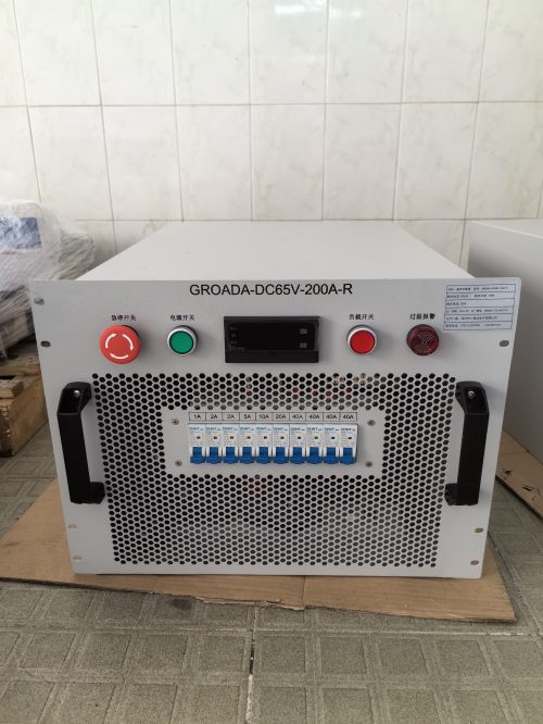
Continuous operation is a thermal and mechanical claim, not a marketing adjective. A load bank rated 1,000 kW for a one-hour test may only be good for 600 kW indefinitely, because the limiting factor is not the resistor alloy but the heat rejection path and the temperature rise permitted at the terminals. Three numbers decide whether a unit belongs in a 24/7 plant room.
The first is the continuous thermal rating at the ambient the unit will actually see — usually 40 °C, sometimes 50 °C in a container yard or tropical generator hall. A serious supplier publishes the derating curve, not just a single nameplate figure. The second is the duty class of every switching device in the load step chain: contactors selected for AC-1 resistive duty at 100% rated current behave very differently from general-purpose devices pushed to their limit. The third is the airflow budget — cubic meters per second through the core, static pressure available to overcome ductwork and filters, and the resulting outlet air temperature, which is often 80–120 °C above ambient and must be ducted or louvered safely.
Beyond those three, 24/7 duty demands intentional design choices: cold-rolled steel with a high-temperature powder coat rather than painted mild steel, ceramic or stainless-clad element supports that do not creep, terminal blocks rated for continuous current rather than peak, separate control and power compartments so electronics do not bake in the exhaust stream, and a PLC that logs element hours so preventive maintenance is based on real data instead of guesswork.
How We Select a Platform for Continuous Duty
Before looking at models, we run every project through the same six questions, because a mismatch in any one of them turns a 24/7 unit into a repair ticket.
Load type. Resistive only (unity power factor, suitable for kW testing of engines, UPS, and DC systems via rectifier front ends), resistive-reactive (0.8 lagging, required to prove kVA and alternator excitation), or hybrid resistive-reactive-capacitive for grid-forming inverters and weak-grid studies. Choosing resistive for a kVA test is the single most common specification error we see.
Voltage class. Low voltage (208–690 V) is the workhorse. Medium voltage (4.16–13.8 kV) removes the step-down transformer and its losses but raises the isolation and switching requirements. DC systems — battery racks, fuel cells, electrolyzers — need a dedicated DC platform with the right minimum voltage for element conduction.
Cooling medium. Forced air is simplest and cheapest to install but dumps 1 kW of heat into the room for every 1 kW of load. Water cooling is compact and near-silent but needs a cooling loop with adequate flow and quality. Air-cooled with inlet and outlet ducting is the compromise most indoor plants choose.
Control and integration. Local touchscreen for commissioning, remote PLC with Modbus TCP or profinet for plant SCADA, and often both, with a hard-wired emergency stop independent of the network. For unattended 24/7 operation the remote interface is not optional; it is how the unit is used 99% of the time.
Environment. Indoor plant room, outdoor pad, ISO container, or trailer deck. Coastal and offshore installations push us toward 316 stainless fasteners, sealed enclosures at IP54 or better, and anti-condensation heaters.
Service access. Element replacement should be possible from one face with the unit de-energized, without removing the fan box. If a technician needs a crane to change a resistor, the platform is wrong for continuous duty.
The Top 8 Heavy-duty Load Bank Platforms
1. HD-R Series — Forced-air Resistive Workhorse (100–2,000 kW)
The platform most of our continuous-duty projects start with. Open-coil nickel-chromium elements are mounted in a rigid stainless frame with ceramic insulators rated well above the working temperature, and the elements are arranged in a matrix that keeps airflow velocity uniform across the core — the usual cause of hot spots and premature failure in cheaper designs. Standard build is 480 V, 60 Hz, with load steps in binary and decimal increments to 1 kW resolution, controlled by a PLC with a 7-inch touchscreen and Modbus TCP. The continuous rating is stated at 50 °C ambient with a published derating curve up to 55 °C. Typical 24/7 use: continuous engine loading in test cells, generator exerciser duty, and data center UPS burn-in.
2. HD-RC Series — Resistive-Reactive at 0.8 Power Factor (250–2,500 kVA)
When the acceptance criterion is kVA rather than kW, the reactive half of the load has to be as durable as the resistive half. The HD-RC uses dry-type iron-core reactors with Class H insulation, tapped for stepped kvar injection, and interlocks that prevent reactive steps from being applied without a matching resistive base — protecting the source from a leading power factor excursion. Continuous duty is supported by thermostatically controlled forced ventilation and reactor winding sensors that alarm before insulation limits are approached. This is the platform for alternator and switchgear proving, marine generator acceptance, and utility peak-shaving plant testing.
3. HD-M Series — Containerized Modular Bank (1–6 MW)
Built inside a 10-foot or 20-foot ISO container with louvered intake, vertical discharge, and internal walk-in access to the element racks. Modules are self-contained and independently fused, so a single element failure does not take the whole bank offline, and capacity can be expanded in 500 kW increments without rebuilding the enclosure. Designed for outdoor pad mounting in ambient up to 45 °C, with anti-condensation heaters, IP54 control compartment, and CCTV-ready interior lighting. This is the platform of choice for multi-megawatt data center commissioning, where the bank may run continuously for weeks during integrated systems testing.
4. HD-W Series — Water-cooled, High-density, Low-noise (200–3,000 kW)
Where airflow is impossible or noise limits are strict — hospital baselines, urban substations, indoor engine halls, offshore modules — the HD-W rejects heat into a closed-loop cooling circuit instead of the room. The element bundle sits in a stainless housing with a flow switch, differential pressure monitor, and inlet/outlet temperature sensors that trip the load if flow falls below the design minimum. Footprint is roughly one third of an equivalent air-cooled bank and sound pressure at one meter is typically below 65 dB(A). Requires a properly sized cooling loop with water quality control; we specify the allowable conductivity and glycol range at order.
5. HD-DC Series — Battery, UPS and Fuel Cell Load Bank (48–1,000 VDC)
DC testing has different failure modes: arc suppression on disconnect, minimum voltage for element conduction at end-of-discharge, and precise constant-current or constant-power control during a capacity test. The HD-DC provides both CC and CP modes with programmable discharge profiles, automatic end-voltage cutoff, and per-cell or per-module voltage monitoring integration. Continuous duty versions use larger element cross-sections to hold current stable as resistance drifts with temperature — important when the acceptance criterion is a discharge curve, not just a load step.
6. HD-MV Series — Medium-voltage Direct Connection (4.16–13.8 kV)
Connecting directly at distribution voltage eliminates the step-down transformer, its losses, and its footprint. The HD-MV is built as a switchgear-adjacent enclosure with vacuum circuit breaker or load-break switch, integral grounding switch, visible isolation, and full interlocking to the load step control. Element banks are arranged in series-parallel groups to keep step resolution fine at high voltage, and the control system enforces a defined step sequence to limit inrush. Every unit ships with a documented dielectric test report and relay settings coordinated with the site protection scheme.
7. HD-P Series — Trailer-mounted Portable Bank (100–600 kW)
Portable does not have to mean light duty. The HD-P is a road-legal trailer with a continuous-duty core, galvanized chassis, and a control panel isolated from the exhaust stream so the electronics survive long summer deployments. Cable lengths up to 30 m are supported with correctly sized lugs, and the unit can be left running unattended with remote monitoring over a cellular gateway. This is the platform for rental fleets, remote substations maintenance, and site generator commissioning where no permanent installation exists.
8. HD-H Series — Hybrid Resistive-Reactive-Capacitive Bank (500 kW–4 MVA)
Grid-forming inverters, battery energy storage systems, and weak-grid interconnections need a load that can swing between lagging and leading power factor quickly and repeatedly. The HD-H combines resistive elements, iron-core reactors, and capacitor banks under a single controller that can execute programmed power-factor sweeps, ramp profiles, and step transients at defined rates. Continuous duty is achieved through thermal modelling per subsystem and independent cooling control, and the controller logs every transition for later analysis. If your acceptance test references fault ride-through, frequency response, or power factor sweep, this is the platform.
Protection and Instrumentation You Should Insist On
For unattended 24/7 operation, protection is what keeps a load bank from becoming a fire risk. At minimum: overtemperature sensing on each element group with a trip ahead of the insulation limit, airflow proving via differential pressure switch, fan motor overload and phase-loss protection, ground fault detection, and a hardware overcurrent trip independent of the PLC. On the instrumentation side, expect true RMS voltage and current measurement per phase, kW, kvar, kVA and power factor computation, energy accumulation, and an event log with timestamps. If the unit will sit on a plant network, demand the register map at the quotation stage — discovering after delivery that the bank only supports a proprietary protocol is an expensive surprise.