
Commissioning a photovoltaic plant is not finished when the last module is torqued down and the inverters are energised. Before the owner signs the takeover certificate, someone has to prove that the plant actually delivers the power it was designed to deliver — under controlled, repeatable, traceable conditions. That is the job of a solar energy load bank. It replaces the grid as the sink for inverter output, lets you dial the array from 0 % to 100 % of rated power in defined steps, and holds that operating point long enough to record stable voltage, current, power, power factor, efficiency and temperature data.
Over the past decade we have supplied and commissioned load banks on rooftop, utility-scale, floating and hybrid PV sites across a wide range of grid codes. The five families below are the ones we recommend most often, and the reasoning behind each is spelled out so you can match a unit to your own testing scope rather than to a specification sheet alone.
Why a PV plant needs a dedicated load bank before handover
Grid-connected inverters cannot be tested properly into an open circuit, and they cannot be tested properly into a weak or unstable grid either. A load bank gives you three things a live grid cannot:
- Deterministic operating points. You can command exactly 37 % of rated power and hold it, which is what IEC 61724-1 performance-ratio work and IEC 62446-1 verification actually require.
- Repetition. The same load step sequence can be run on every inverter on site, so efficiency and thermal data are comparable between units and between commissioning and the one-year warranty test.
- Grid-code evidence. Reactive current injection, power factor range, voltage ride-through recovery and anti-islanding behaviour all need a controllable, programmable load or a controllable source-load combination to be demonstrated and documented.
Where a plant is connected to a strong grid, the load bank still earns its place during capacity testing, because the alternative — waiting for a clear-sky noon and hoping the irradiance stays inside the correction window — is neither schedulable nor defensible in a test report.
What actually matters when you select a unit
| Parameter | Why it decides the purchase |
|---|---|
| DC or AC side | DC load banks test strings, combiners and the DC input stage; AC load banks test inverter output, transformer and plant-level performance. Most commissioning scopes need AC; module and string diagnostics need DC. |
| Voltage window | 1500 V DC systems are now standard on utility-scale plants; 1000 V DC remains common on older rooftops. AC units must cover 400 V, 690 V or the medium-voltage level after the step-up transformer. |
| Power steps and resolution | Fine resolution (1 kW or better at low ratings, 10–25 kW at megawatt ratings) is what makes part-load efficiency curves and MPPT sweeps meaningful. |
| Load character | Resistive only for capacity and thermal tests; resistive plus reactive for power factor, reactive capability and ride-through work. |
| Duty cycle and cooling | A unit rated 1 MW continuous is not the same as a unit rated 1 MW for ten minutes. Force-ventilated resistors with thermal derating data are what you want for multi-hour capacity tests. |
| Control and logging | Local HMI is convenient; Modbus TCP, CAN or IEC 61850 with time-stamped logging is what produces an auditable test record. |
| Mobility | Containerised skid, trailer-mounted or handheld — this is decided by how far apart the test points are and whether site roads can carry the weight. |
1. LB-SD series — 1500 V DC solar load bank for string and combiner testing
The LB-SD is the unit we send out when the question is about the DC side of the plant: string current matching, combiner box behaviour, DC arc-fault response and inverter MPPT tracking accuracy. It accepts up to 1500 V DC and is built around a forced-air resistor stack with solid-state switching, so it can step in 1 kW increments at low power and 25 kW increments at full rating.
- Voltage range: 200–1500 V DC, with a 1000 V variant for older rooftops
- Power ratings: 100 kW, 250 kW and 500 kW frames
- Step resolution: 1 kW minimum, 0.1 % of full scale repeatability
- Control: local touchscreen plus Modbus TCP; scriptable step sequences for MPPT sweeps
- Protection: DC breaker, reverse polarity, over-temperature, ground-fault detection, IP54 enclosure
Its practical value shows up in MPPT verification. By sweeping the load from 10 % to 100 % in small steps and logging the inverter's reported maximum power point against the measured array curve, you get a direct statement of tracking efficiency rather than a claim from the datasheet. On a 100 MW plant this is typically done on a statistical sample of inverters, and the LB-SD's wheeled frame makes that sample practical in a single day.
2. LB-SA series — AC load bank for inverter output and plant capacity testing
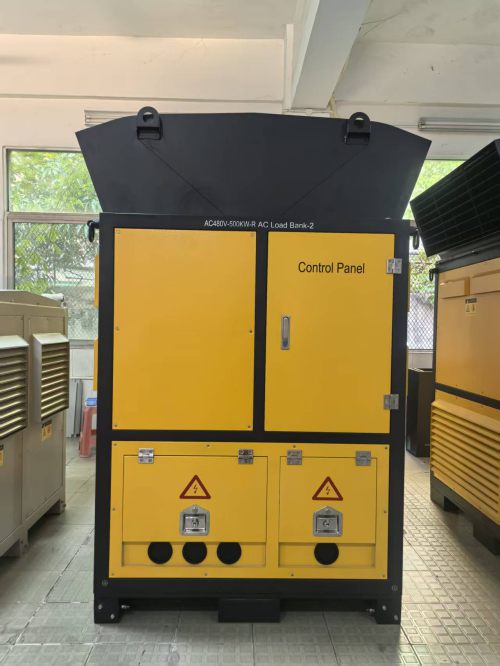
This is our workhorse for inverter-level and block-level capacity tests. Ratings run from 250 kW to 1.25 MW in a single skid, with parallel operation for larger blocks. The load is resistive by default; add-on reactive modules bring inductive and capacitive capability for power factor work.
- Voltage: 400 V / 480 V / 690 V three-phase, 50 or 60 Hz
- Power: 250 kW to 1.25 MW per unit, up to 8 units paralleled
- Resolution: 1 kW steps, 0.5 % accuracy on measured power
- Cooling: horizontal forced-air, 50 °C ambient rating with published derating curve
- Control: PLC-based controller, Modbus TCP / RTU, optional IEC 61850 for plant-level integration
- Recording: 1 s sampling with CSV export and time-stamped test reports
For capacity testing we run the standard sequence: stabilise at 25 %, 50 %, 75 % and 100 % of rated AC power, hold each point for a minimum of ten minutes after thermal equilibrium, and record irradiance, module temperature, AC power and power factor simultaneously. The measured values are then corrected to standard test conditions using the procedure in IEC 60891, which is only defensible if the load points themselves were stable — and that is the entire argument for a load bank over a grid-connected test.

3. LB-MV containerised series — medium-voltage load bank for plant-level and grid-code testing
Once you are testing at the point of interconnection, you are working at 10 kV, 33 kV or 35 kV and at multi-megawatt scale. The LB-MV puts the resistive and reactive elements, the step-up transformer and the switchgear inside a 20 ft or 40 ft container, delivering 2.5 MW to 10 MW of controllable load at medium voltage.
- Voltage: 6 kV to 35 kV, transformer-integrated
- Power: 2.5 MW, 5 MW and 10 MW configurations
- Load character: resistive, inductive and capacitive banks selectable independently, enabling 0.9 leading to 0.9 lagging power factor across the full power range
- Control: remote SCADA with sequence programming, suitable for ride-through and ramp-rate test profiles
- Cooling: containerised forced ventilation with louvre control and acoustic attenuation for residential-adjacent sites
This is the family we deploy for grid-code compliance demonstrations. Reactive capability curves, voltage and frequency ride-through recovery, active power ramp rates and set-point accuracy all become measurable events rather than simulations. Because the reactive bank is independently selectable, the same container can hold a fixed power factor while the active power steps, which is exactly the profile most grid operators ask for in the compliance test procedure.
4. LB-PC portable series — compact load bank for rooftop and distributed PV
Rooftop and carport installations rarely have the space or the floor loading for a skid-mounted unit. The LB-PC is a 30 kW to 100 kW portable load bank in a wheeled aluminium case, small enough to move through a plant room and light enough for two technicians to lift onto a lift.
- Voltage: 400 V AC three-phase, or 1000 V DC input variant
- Power: 30 kW / 50 kW / 100 kW
- Resolution: 0.5 kW steps
- Weight: 45–90 kg depending on rating
- Control: handheld controller with 20 m cable, plus Bluetooth app for remote stepping
For distributed-generation portfolios this is the unit that gets used weekly rather than annually. It handles inverter verification on a 200 kW commercial rooftop in an afternoon, and it doubles as a discharge load for battery storage commissioning on hybrid sites.
5. LB-RL reactive load bank — for power factor, harmonics and inverter stress testing
The fifth family exists because active power testing only tells half the story. Modern inverters are expected to inject reactive current, ride through voltage disturbances and stay stable at low short-circuit ratio. The LB-RL combines resistive, inductive and capacitive elements with fast switching so that power factor can be stepped while active power is held constant.
- Power: 500 kVA to 3 MVA combined resistive and reactive
- Power factor range: 0.3 leading to 0.3 lagging, continuously selectable in steps
- Switching: thyristor-stepped reactive elements for sub-cycle changes
- Optional harmonic injection module for immunity testing to IEEE 1547 and local equivalent standards
- Instrumentation: class 0.2 power analyser integrated, with harmonic spectrum capture up to the 50th order

Side-by-side comparison
| Model | Side | Power range | Load type | Typical use |
|---|---|---|---|---|
| LB-SD | DC, ≤1500 V | 100–500 kW | Resistive | String, com
Continue Reading |