
Why Wind Turbine Output Detection Cannot Be Done Without a Load Bank
A wind turbine only proves what it can do when it is actually loaded. In the field, that is almost impossible to arrange on demand: wind speed is intermittent, grid operators restrict export during commissioning windows, and a turbine that is connected to the grid cannot be pushed to its limits for hours at a time just to satisfy a test schedule. A wind power load bank solves this by providing a controllable, repeatable, fully absorbing electrical sink that turns turbine output into heat — and, in reactive versions, into inductive or capacitive current — regardless of what the wind is doing outside the nacelle.
This is why load banks have moved from being a commissioning accessory to a core piece of test equipment across the wind industry. They are used for nacelle and drivetrain factory acceptance testing, generator and converter validation, pre-grid-connection commissioning, power curve verification under IEC 61400-12-1, grid code compliance measurement under IEC 61400-21, fault diagnosis after gearbox or blade repair, and long-term burn-in of prototype platforms. In each case the requirement is the same: a load that is stable, finely adjustable, thermally durable and safe to leave running unattended.
What a Wind Power Load Bank Actually Has to Do
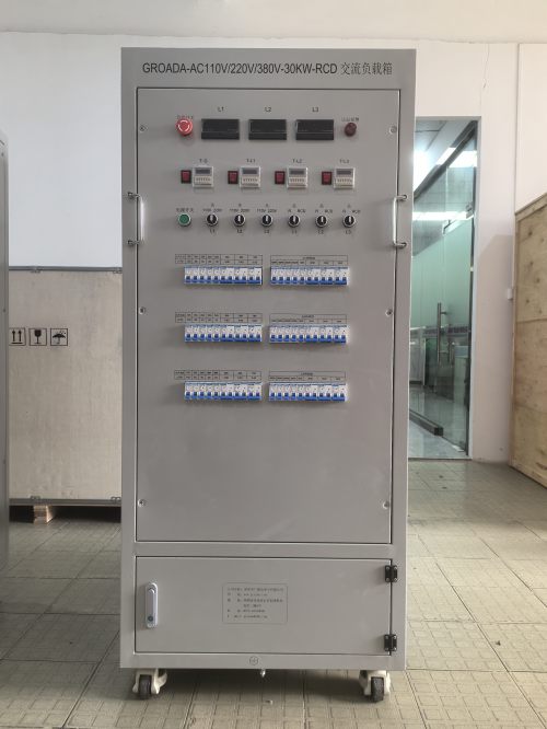
A wind turbine load bank is not simply a big resistor. It has to match the electrical envelope of the turbine, survive continuous duty at rated current, and communicate with the test team's data acquisition system. When we specify a unit for a turbine platform, we work through the same checklist every time:
- Voltage and frequency window. Most onshore platforms operate at 690 V, with 400 V auxiliaries and medium-voltage export at 33 kV or 35 kV. Offshore units frequently sit at 66 kV. The load bank must accept the full operating range, not just the nominal point.
- Power rating and step resolution. Rated power sets the ceiling; step resolution sets the quality of the test. A 5 MW bank that can only switch in 500 kW blocks cannot measure part-load behaviour or converter efficiency curves.
- Load character. Pure resistive loading tests active power and thermal behaviour. Resistive-reactive loading with a power factor range of 0.8 lagging to 0.8 leading is required to verify converter reactive capability and grid code compliance.
- Cooling and duty cycle. Forced-air cooling is standard; the derating curve for ambient temperature and altitude matters more than the headline rating.
- Control and communications. Local HMI plus Modbus TCP, Profinet or Ethernet/IP, with analogue and digital I/O for synchronising with the turbine controller and the data logger.
- Protection and environmental rating. Over-temperature, over-current, fan failure, phase sequence, earth fault, door interlocks. IP54 as a baseline, C5-M corrosion protection for offshore.
Our Top 6 Wind Power Load Banks
1. WP-R Series Containerized Resistive Load Bank (1 MW to 6 MW)
The workhorse of nacelle and drivetrain testing. Built into a standard 20 ft or 40 ft container, the WP-R series delivers continuous resistive load at 690 V with step resolution down to 10 kW, which is fine enough to hold a turbine at any point between cut-in and rated power. Nichrome resistance elements are mounted in an insulated, forced-air-cooled stack with horizontal discharge, so the unit can be sited close to the turbine base without recirculating hot air into its own intake. Control is by PLC with a touchscreen HMI, and load steps can be commanded manually, from a script, or remotely over Modbus TCP. Typical use: full-power burn-in, thermal stabilisation of the converter, and power curve points above rated wind speed.
2. WP-RC Series Resistive-Reactive Load Bank (0.5 MW to 3 MW)
Where the WP-R handles active power, the WP-RC adds a reactor bank that can be switched in 1 kvar steps to present a power factor anywhere from 0.8 lagging to 0.8 leading. This is the unit we supply for grid code compliance testing and for converter validation, because it is the only way to prove reactive capability, voltage ride-through behaviour and harmonic performance without asking the grid operator for permission. Resistive and reactive sections can be operated independently, which allows a turbine to be held at a fixed active power while the reactive setpoint is swept — exactly the sequence IEC 61400-21 measurement procedures call for.
3. WP-M Series Modular Skid Load Bank (100 kW to 500 kW per module)
Not every test happens at a wind farm. The WP-M is a skid-mounted module that can be moved by forklift, lifted by crane, or stacked, and paralleled with up to twelve identical units to build a bank of any size. This modularity suits nacelle assembly halls, converter test benches and service depots where the turbine under test changes from week to week. Each module carries its own controller and current transformer, and master-slave paralleling keeps the total load balanced across units without operator intervention.
4. WP-HV Series Medium-Voltage Load Bank (10 kV to 35 kV)
Testing at the collector feeder or at the turbine's medium-voltage terminals requires a load bank that connects directly at 33 kV or 35 kV, avoiding the cost and losses of a step-down transformer. The WP-HV series uses vacuum contactors, a rated insulation level matched to the system voltage, and full interlocking to the upstream breaker. It is typically used for substation and collector commissioning, reactive compensation verification, and back-feed testing where the entire string of turbines has to be loaded as a group.
5. WP-LV Series Portable Low-Voltage Load Bank (50 kW to 300 kW)
A compact, wheel-mounted unit for commissioning engineers and troubleshooting teams. At under 400 kg, the WP-LV can be transported in a service van and connected at 400 V or 690 V through Camlock or terminal studs. It is the practical choice for verifying auxiliary systems, testing small turbines and distributed generation units, checking generator output after a repair, and confirming that a suspect converter is genuinely underperforming rather than merely reporting a fault. A built-in data logger records voltage, current, power and energy for every test run.
6. WP-DC Series DC Link Load Bank (100 kW to 2 MW)
Full-converter and medium-speed drivetrains are increasingly tested at the DC bus rather than at the AC terminals, because that is where the generator-side and grid-side converters meet. The WP-DC provides a controllable DC load from 600 V to 1200 V with continuous current regulation, allowing the generator and rectifier to be characterised independently of the grid-side inverter. It is the standard instrument for converter bench testing, generator efficiency mapping, and fault replication on the DC link.
Matching a Load Bank to a Turbine Platform
The most common specification error is sizing a load bank to the turbine's nameplate rating and stopping there. In practice, three numbers decide whether a unit will perform: the maximum continuous current at the lowest expected voltage, the derating factor at the site's maximum ambient temperature and altitude, and the step resolution needed to resolve the test points of interest. A load bank rated at 5 MW at 25 °C and sea level may be a 4 MW machine at 45 °C and 1500 m. Ask for the derating curve before comparing quotations, and check that the cooling airflow of a containerized unit is not obstructed by the turbine tower or by a second container placed alongside it.
Reactive capability deserves the same scrutiny. A converter that claims 0.9 power factor may only achieve it over a narrow band of active power, and a load bank that cannot independently vary P and Q will never reveal the limits of that band.
A Standard On-Site Test Sequence
With the load bank sited, earthed, and cabled with conductors sized for continuous current rather than short-time current, a typical detection run proceeds in four stages. First, a low-load soak at 10–20 % of rated power to confirm phase rotation, control response and instrumentation. Second, a stepped ramp in 10 % increments, holding each point for at least ten minutes so the turbine's thermal model can settle and the data logger can record a stable average. Third, a sustained run at rated power for two to four hours, which is where generator winding temperatures, converter junction temperatures and cooling performance are genuinely tested. Fourth, a controlled ramp-down with reactive sweeps if the platform requires it. Every stage should be logged synchronously with turbine SCADA data, because the value of the test comes from correlating electrical output with nacelle conditions.
Common Pitfalls and How to Avoid Them
- Undersized cabling. Voltage drop across a long cable run distorts the measured power and heats terminals; size for continuous current and keep runs short.
- Gust-driven overshoot. A turbine can briefly exceed rated output; leave 10 % headroom in the load bank rating.
- Condensation in offshore storage. Specify anti-condensation heaters and run the fans periodically during idle periods.
- Ignoring harmonics. Converter-driven tests inject harmonic current that heats resistive elements unevenly; verify the element design and the current transformer class.
- No interlock with the turbine controller. A load bank that trips without signalling the turbine leaves it exporting into an open circuit.
Frequently Asked Questions
Can a load bank be used while the turbine is grid-connected? Yes, provided the load bank is connected through an approved changeover arrangement and the export limit is respected. Many commissioning scopes run the turbine in parallel with the grid and use the load bank to absorb the portion the grid cannot accept.
How much maintenance does a wind power load bank need? Element inspection and torque checks on terminals annually, fan bearing service every two years, and a full insulation resistance test after any transport or long idle period. Offshore units benefit from an annual corrosion inspection of the enclosure.
Resistive or resistive-reactive — which should we buy first? If your scope is thermal and active-power testing, start with resistive. If grid code compliance or converter reactive capability is on the roadmap, buy the combined unit; retrofitting a reactor bank later usually costs more than the original difference.
Choosing the right wind power load bank comes down to three questions: what electrical envelope must be absorbed, how finely it must be adjusted, and where the unit will physically stand. Answer those honestly and the six platforms above will cover every stage of a turbine's life, from the assembly hall to the last commissioning test on site.