
Standby power systems are only as good as the last time you proved them under real electrical stress. A generator that idles smoothly at 30% load tells you almost nothing about how it behaves the instant a 1 MW chiller bank slams onto the bus, or how fast a UPS transfers when a feeder trips. Emergency load banks for fault simulation exist to close that gap — they replace the unpredictable, dangerous "real load" of a live facility with a controllable, repeatable, and fully instrumented electrical burden.
This guide walks through the seven load bank platforms our engineering team deploys most often for fault simulation work, what each one is actually good at, and how to match a bank to the fault scenarios you need to reproduce.
Why Fault Simulation Beats Conventional Load Testing
Traditional load bank testing verifies capacity: the generator makes its rated kW at its rated power factor, the coolant temperature stabilizes, and the test is signed off. Fault simulation asks a harder question — what happens in the first 300 milliseconds?
The scenarios that actually take down data centers, hospitals, and substations rarely involve steady-state overload. They involve:
- Step loading — a block of load applied in a single switching event, testing voltage and frequency dip recovery against ISO 8528 transient limits.
- Load rejection — full load dropped instantly, exposing overspeed and overvoltage behaviour on the engine and AVR.
- Reactive power transients — a leading power factor event from capacitive loads, testing excitation response and possible loss-of-field protection.
- Short-duration faults — a controlled low-impedance event that forces protective relays and breaker coordination to prove themselves.
- Transfer and re-transfer timing — ATS sequences under load, where a 200 ms delay is the difference between a clean ride-through and a crashed server rack.
Each of these demands a load bank with fast step resolution, genuine reactive capability, and transient capture instrumentation. A resistive-only box rated for continuous duty is not the right tool for any of them.
What to Look For Before You Buy
Across seven platforms the selection criteria stay remarkably consistent. We screen every candidate against six parameters:
| Parameter | Why It Matters for Fault Simulation | Typical Target |
|---|---|---|
| Step resolution | Determines how finely you can shape a load ramp or a single block step | 1% or finer of rated capacity |
| Switching speed | Contactor or IGBT switching defines the fastest transient you can create | < 100 ms; < 10 ms for semiconductor |
| Power factor range | Resistive-only banks cannot reproduce lagging or leading reactive events | 0.8 lagging to 0.9 leading |
| Transient recording | Without waveform capture you cannot document recovery time | ≥ 10 kHz sampling, 3-phase V and I |
| Duty cycle | Fault sequences run hot and back-to-back | Continuous at rated ambient |
| Control interface | Automated sequences need remote and scripted control | Modbus TCP / Ethernet / PLC I/O |
The Top 7 Emergency Load Banks
1. The 500 kW Workhorse Resistive Bank
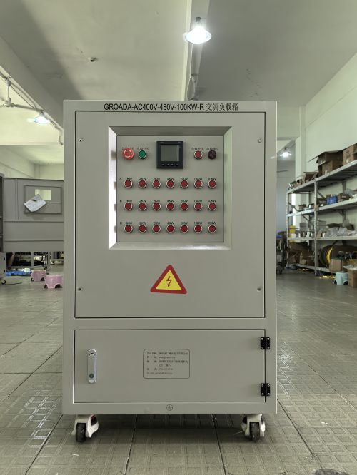
Every fleet needs one bank that gets used weekly and never complains. Our 500 kW air-cooled resistive unit is that machine: 480 V three-phase, 1% step resolution down to 5 kW, and a footprint that fits through a standard double door. It is the default choice for step-load and load-rejection testing on 400–600 kW standby gensets.
Where it earns its place in fault simulation is repeatability. Because the resistive elements are fixed and the step matrix is discrete, two tests run six months apart produce directly comparable transient traces — something you cannot achieve with building load.
- Best for: generator acceptance testing, blackout drills, routine readiness verification
- Watch out for: no reactive capability; pair it with a reactor bank for power factor work
2. The 1.25 MW Combined Resistive-Reactive Bank
When the test plan includes power factor events, a resistive-only bank stops being useful. This 1.25 MW platform adds a switched reactor bank with a 0.8 lagging capability and an optional capacitor stage for leading power factor, letting you hold the alternator at its rated kVA rather than its rated kW.
For fault simulation this matters in one specific, high-value way: excitation system stress. Running a generator at 0.8 pf exposes AVR response, field forcing limits, and rotor heating that a unity-power-factor test never touches. If you are commissioning a unit that will carry motor-heavy load, this is the bank the test plan should specify.
"A generator proven at 1.0 pf has demonstrated about 80% of its thermal capability. The reactive test is not optional — it is the part of the acceptance test that finds the problems."
3. The 300 kW Modular Portable Bank
Fault simulation is not always a scheduled event. For field service teams, the modular 300 kW platform breaks into four 75 kW sections that two technicians can move on casters and reconnect in under an hour. Each section has its own breaker and step controller, so the bank can be configured as a single 300 kW block or as four independently switched steps for sequenced load ramps.
This is the platform we send when the customer's switchgear room has no clear floor space and the generator sits in a basement with a 900 mm doorway. Practical constraints decide more test outcomes than datasheets do.
4. The 6 MVA Medium-Voltage Bank
Above 1 kV, load bank selection becomes a switchgear problem as much as an electrical one. The 6 MVA medium-voltage platform operates directly at 13.8 kV (with 4.16 kV and 6.6 kV variants), eliminating the step-down transformer losses — and the transformer's own impedance, which otherwise distorts the very transient you are trying to measure.
Fitted with vacuum contactor switching and integrated CT/VT inputs, it supports substation-scale fault simulation: full-load rejection on a utility-owned generator, protective relay coordination checks, and black-start verification on plant distribution systems.
Safety note: MV fault simulation requires a written switching programme, lockout procedures, and an arc-flash study updated for the test configuration. Never treat an MV load test as an extension of an LV procedure.
5. The 200 kW DC Bank for UPS and Battery Systems
Not every emergency power system spins. For battery strings, DC bus systems, and large UPS installations, the relevant fault is a battery capacity collapse under discharge or an inverter transfer anomaly — neither of which a three-phase AC bank can test.
This 200 kW DC platform discharges at constant current, constant power, or a programmed profile, logging cell-level voltage if the BMS exposes it. The constant-power mode is the important one: it reproduces the actual behaviour of a UPS inverter drawing from a battery string, where current rises as terminal voltage falls.
6. The Transient and Fault Sequence Simulator
This is the platform built specifically for the article's subject. Using IGBT switching rather than contactors, it applies and removes load in under 10 ms and can execute a stored sequence — step, hold, reject, step, reject — without an operator in the loop.
Capabilities worth noting:
- Programmable transient profiles with dwell times from 10 ms to 60 minutes
- Synchronized waveform capture at 20 kHz across all three phases plus field current
- Sequence library for ISO 8528-5 G1/G2/G3 compliance runs and IEEE 1547 ride-through profiles
- Automated pass/fail reporting against voltage and frequency recovery envelopes
If your commissioning documentation needs to show that a generator recovered to within ±10% voltage and ±2% frequency inside a specified window, this is the instrument that produces that evidence automatically rather than from a hand-annotated oscilloscope screenshot.
7. The 2 MW Containerized Bank
The last entry is the one we deploy for multi-day, high-power campaigns: a 2 MW containerized resistive-reactive bank with onboard transformers, chiller-cooled elements, and a control room. It ships as a single ISO container, connects at MV or LV, and runs continuously in ambient temperatures up to 50 °C.
Its role in fault simulation is endurance under repeated transients. Data center commissioning often requires dozens of transfer tests in sequence — utility to generator, generator to utility, generator to generator — and the bank must absorb that duty cycle without thermal derating. Containerized banks are built for exactly this.
Comparison at a Glance
| # | Platform | Rating | Switching | Best Fault Scenario |
|---|---|---|---|---|
| 1 | Resistive workhorse | 500 kW | Contactor, 100 ms | Step load, load rejection |
| 2 | Resistive-reactive | 1.25 MW @ 0.8 pf | Contactor, 100 ms | Excitation stress, reactive transients |
| 3 | Modular portable | 300 kW (4 × 75) | Contactor, 150 ms | Sequenced ramps, confined spaces |