Our Top 5 Resistive Capacitive Load Banks for Power Factor Correction Testing
Power factor correction testing sits at the heart of validating modern electrical infrastructure, from data center UPS systems to renewable energy inverters. As a load cell and load bank engineer, I have watched leading and lagging power factor requirements grow more demanding across the industry. Resistive capacitive load banks are the tools that make realistic simulation of these conditions possible. In this white paper, I break down what makes a resistive capacitive load bank effective and share our top five picks for power factor correction testing.
Why Resistive Capacitive Load Banks Matter
Traditional resistive load banks only simulate unity power factor loads. Real-world electrical systems, however, rarely operate at a power factor of 1.0. Data centers, telecommunications equipment, and switch-mode power supplies frequently present leading power factor loads to their source. To validate that a generator, UPS, or inverter can handle these conditions, you need a load bank capable of drawing both resistive (real) and capacitive (reactive) power.
A resistive capacitive load bank combines resistive elements with capacitor banks, allowing test engineers to reproduce leading power factor conditions ranging typically from 0.8 to unity. This is essential for verifying voltage regulation, transient response, and thermal stability under the reactive loading that today's electronic equipment imposes on power sources.
Key Selection Criteria
Before reviewing our top five, it helps to understand what separates a capable unit from a compromised one. When we evaluate resistive capacitive load banks in our own lab, we weigh five factors:
- Power factor range: The breadth of leading power factor the unit can achieve, and how finely it can be adjusted in steps.
- Capacity and modularity: Rated kW and kVAR, plus the ability to combine units for higher-capacity testing.
- Control and instrumentation: Precision of load stepping, remote control interfaces, and real-time metering accuracy.
- Cooling and duty rating: Whether the unit sustains continuous operation without derating under high reactive load.
- Safety and protection: Overcurrent, overtemperature, and capacitor discharge safeguards.
1. High-Capacity Modular RC Load Bank
Our first pick is the modular high-capacity resistive capacitive load bank designed for large UPS and generator commissioning. Rated up to 1000 kW resistive with 750 kVAR of capacitive loading, it delivers leading power factor down to 0.8. The standout feature is its modular architecture. Each cabinet couples independently, so a test team can scale from a single 250 kW unit to a multi-megawatt bank without changing control philosophy.
Fine-grained load stepping, often in 1 kW and 5 kVAR increments, lets engineers walk through power factor curves rather than jumping between coarse setpoints. This granularity is invaluable when characterizing voltage regulation behavior at the margins of a UPS specification. Forced-air cooling with redundant fans supports continuous full-load operation, which matters for extended burn-in and endurance tests.
2. Portable Resistive Capacitive Load Bank
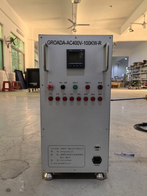
Field service teams face a different challenge: they need capacitive loading on-site without a crane. Our second pick is a portable resistive capacitive load bank in the 100 to 300 kW class. Mounted on a wheeled chassis with lifting eyes and forklift pockets, it brings leading power factor testing directly to the installation.
Despite its compact footprint, this class of unit provides genuine capacitive load rather than a purely resistive substitute. It typically offers a leading power factor of 0.9 across its range, sufficient for validating small to mid-size UPS systems and telecom power plants. Integrated metering displays kW, kVAR, voltage, current, and calculated power factor, giving the field technician immediate feedback without external instruments.
3. Precision Laboratory RC Load Bank
For R&D and type-testing environments, precision outranks raw capacity. Our third pick is a laboratory-grade resistive capacitive load bank built around tightly toleranced resistive and capacitive elements. Load accuracy in the range of plus or minus one percent, combined with programmable load profiles, makes it ideal for repeatable qualification testing.
This unit shines when a test plan calls for automated power factor sweeps. Through a programmable controller, engineers script sequences that step resistive and capacitive load in coordination, holding a target power factor while ramping total apparent power. That capability turns a full day of manual adjustment into an unattended overnight run, and it produces the consistent data sets that certification bodies expect.
4. Combined Resistive Inductive Capacitive Load Bank
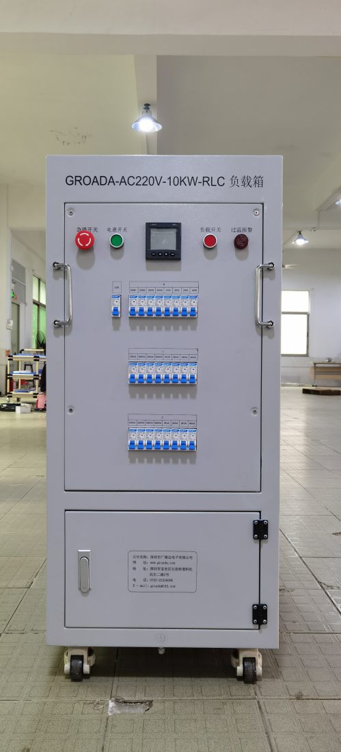
Some applications require both leading and lagging power factor in a single test session. Our fourth pick is a combined resistive inductive capacitive load bank, sometimes called an RLC load bank. By integrating inductive elements alongside the capacitive stage, it simulates the full spectrum of real-world loading, from lagging motor loads to leading electronic loads.
This versatility suits comprehensive generator acceptance testing where a single machine may serve mixed loads over its life. The ability to transition from a 0.8 lagging condition to a 0.9 leading condition within one setup reveals how a generator's automatic voltage regulator and governor respond to reactive swings. For microgrid and hybrid renewable projects, this breadth of testing is increasingly a contractual requirement.
5. Automated Networked RC Load Bank
Our fifth pick addresses the trend toward remote and unattended testing. This networked resistive capacitive load bank exposes full control over Ethernet, Modbus TCP, and often a web interface. Test engineers configure and monitor power factor correction runs from a control room or across a corporate network, which is valuable when the load bank sits in a hazardous or isolated test cell.
Data logging is where this unit earns its place. Every load step, measured power factor, voltage, and temperature is timestamped and stored, then exported for reporting. When a customer needs traceable evidence that their UPS held regulation at 0.85 leading power factor across a defined duty cycle, this automated record removes any ambiguity. Integration with SCADA and test-management software further streamlines high-volume production testing.
Matching the Load Bank to Your Application
No single resistive capacitive load bank suits every task. High-capacity modular units serve data center and large UPS commissioning. Portable units bring capacitive loading to the field. Laboratory-grade units deliver the precision that R&D and certification demand. Combined RLC units cover the full reactive spectrum, and networked units enable automated, traceable testing at scale.
When specifying a unit, start from the power factor range your standard requires, then confirm the kW and kVAR ratings cover your largest device under test with margin. Verify that the cooling and duty rating support your test duration, and never overlook capacitor discharge safety, because stored energy in a capacitor bank is a genuine hazard that proper design must manage.
Conclusion
Power factor correction testing is only as reliable as the load bank behind it. Choosing a resistive capacitive load bank that matches your capacity, precision, and control needs ensures that your generators, UPS systems, and inverters perform as promised under real reactive loading. The five options above represent the configurations we return to most often, each optimized for a distinct testing context. Invest in the right one, and your power factor validation moves from guesswork to documented certainty.