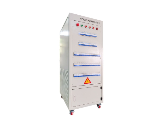
GROADA-AC380V-50KW-R/RCD逆变器负载组
The GROADA AC380V-50KW-R/RCD inverter test load bank is a high-performance testing device specifical...

| 模型 | AC220V-5KW-RCD | AC220V-10KW-RCD | AC220V-15KW-RCD | AC220V-20KW-RCD | 交流380v-30千瓦/日 | 交流380v-50KW-RCD | 交流380v-60KW-RCD | 交流380v-100KW-RCD | 交流380v-200KW-RCD |
| 额定功率 | R=5KW | R=10KW | R=15KW | R=20KW | R=30KW | R=50KW | R=60KW | R=100KW | R=200KW |
| RCD=5KVA | RCD=10KVA | RCD=15KVA | RCD=20KVA | RCD=30KVA | RCD=50KVA | RCD=60KVA | RCD=100KVA | RCD=200KVA | |
| 输入电流 | 0-22A | 0-45A | 0-45A | 0-90A | 0-45A | 0-3:00 | 0-450A | 0-600A | 0-750A |
| 尺寸(宽*深*高mm) | 500*600*800 | 500*600*1000 | 500*600*1100 | 500*750*1100 | 600*850*1400 | 600*850*1600 | 600*850*1850 | 700*1000*1800 | 1100*1400*1800 |
| 重量 | 50KG | 80公斤 | 100公斤 | 130公斤 | 200KG | 300公斤 | 350公斤 | 450公斤 | 550公斤 |
| 输入电压 | 交流220/230V | 交流380/400V | |||||||
| 其他输入电压可根据要求定制 | |||||||||
| 最小载荷 | 100W | 100W | 100W | 100W | 100W | 1千瓦 | 1千瓦 | 1千瓦 | 1千瓦 |
| 其他最小负载功率可根据要求定制 | |||||||||
| 整体精度 | 3%(其他精度要求可根据要求定制) | ||||||||
| 功率因数 | PF=0.6~1.0 | ||||||||
| 峰形系数 | 2至3 | ||||||||
| 控制模式 | 本地手动/远程主机(本地手动控制模式:断路器/按钮/触摸屏三路可选,其他方法可根据需要定制) | ||||||||
| 远程接口 | RS232/RS485/USB/RJ45/CAN/GPIB(其他接口模式可根据要求定制) | ||||||||
| 保护功能 | 紧急停机保护、超温保护、风机负载联锁保护、接地保护(选择过压保护、过流保护、短路保护、风机超负荷、风量不足) | ||||||||
| 工作电源 | AC220V | AC220V/AC380V | |||||||
| 显示精度 | 0.5级(其他显式精度可根据要求定制) | ||||||||
| 显示参数 | 电压、电流、功率、频率、功率因数等。(其他显式方法可根据要求定制) | ||||||||
| 冷肯定的方式 | 侧进风口和上出风口(其他出风口方式可根据要求定制) | ||||||||
| 保护级别 | IP20(其他防护等级可根据要求定制) | ||||||||
| 外观颜色 | RAL7035(其他颜色可根据要求定制) | ||||||||
| 工作温度 | -10 ℃ ~ 55 ℃ | ||||||||
| 相对湿度 | ≤95%相对湿度 | ||||||||
| 高度 | ≤2500米 | ||||||||
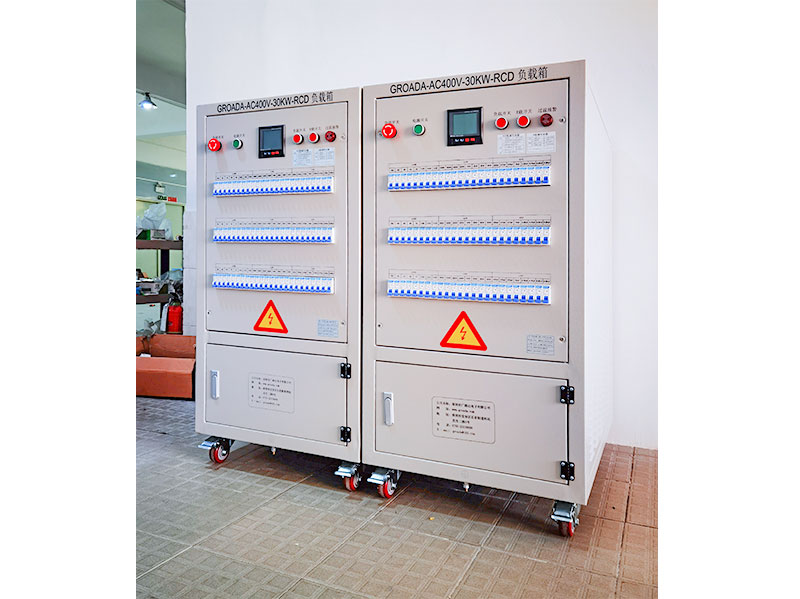
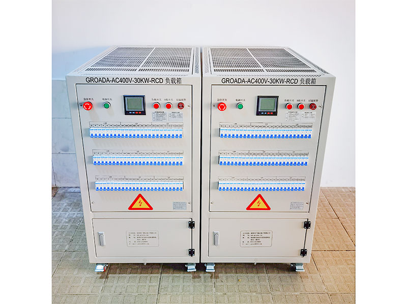
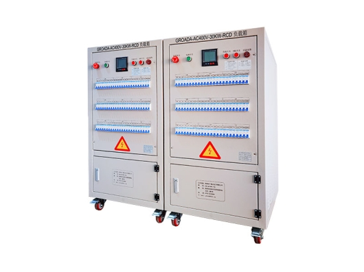
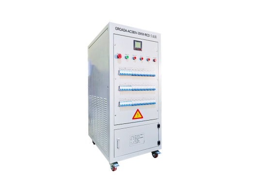
在电力电子和可再生能源系统中,逆变器性能的精确验证是必不可少的。这AC 400 V/30 kW RCD逆变器负载组设计用于为逆变器验证、诊断和校准提供可靠、可控的测试负载。本产品专为R&;D、 质量控制、制造和现场服务环境。
本页解释了技术原理、测试用例、性能规范和行业最佳实践,以帮助工程师、项目负责人和决策者做出明智的选择。
负载组通过从被测逆变器中提取受控电流来模拟电气负载,将提取的功率转换为热量(或其他形式),同时允许测量电压、电流、功率、效率和动态行为。简而言之:它充当受控的“虚拟负载”,对逆变器施加压力并揭示性能特征。
这类似于用于发电机或UPS系统的标准负载组。
在逆变器测试中(特别是对于光伏(PV)系统、电机驱动器或混合动力系统),负载组有助于确认逆变器可以:
满载时维持额定输出
处理瞬态负载变化
保持波形质量、电压和;频率稳定性
触发保护功能(过载、过压、超温)
在长时间或气候压力下可靠运行
准确的负载测试是将逆变器部署到现场之前的关键步骤,以确保安全性、可靠性和保修保证。
逆变器测试中使用的负载模拟大致有两类:
被动/电阻负载--简单的电阻负载(纯电阻)简单、稳定且成本效益高。它们适用于基线性能测试。
主动/被动/可编程负载--更先进的负载,可以模拟电感、电容、类似电机的行为、变化的功率因数、瞬态行为和双向电流。在实际条件下测试逆变器时(例如,使用电机、电网交互),这些是必不可少的。
例如,可编程交流负载(有源交流负载)可以动态地改变其阻抗,从而能够在不同的负载场景(电阻、电感、混合)下进行测试。
负载类型的选择取决于目标应用(太阳能、电动汽车、电机驱动)和所需的测试范围。
下面是您可以为产品页面调整或扩展的规范和功能内容的建议结构。
| 参数 | 典型值/范围 | 重要性/注意事项 |
|---|---|---|
| 标称输出电压 | 380–480 V AC (or adjustable around 400 V) | Must match inverter output voltage to avoid mismatch |
| 额定功率 | 30千瓦 | Allows testing inverters up to this power class |
| Load control mode | Constant power / constant current / constant impedance | Versatility in various load profiles |
| Power factor range | 0.8 lag to 0.8 lead (or full range) | To emulate inductive or capacitive loads |
| Cooling method | Forced air / water-cooled | For thermal management under high load |
| Accuracy / measurement precision | e.g. ±0.5 % for current/voltage | Ensures accurate performance evaluation |
| Response time / dynamic bandwidth | e.g. <1 ms, or specified slew rate | Important for transient load changes |
| Protection & safety | Overload, overtemperature, overvoltage, short-circuit | Safeguards both load unit and inverter |
| Communication & control interfaces | RS-485, CAN, Ethernet, Modbus, SCPI | For remote control, automation, integration |
| Cooling / ambient support | Operation range (e.g. –20 °C to +60 °C) | Ensures performance under field-like conditions |
| Mechanical design | Compact modular racks, ease of integration | Facilitates adoption in test benches |
In your page, you can present these specifications clearly, with callouts (e.g. “Why this matters”), diagrams, and even downloadable PDF spec sheets.
You should also highlight unique selling points (USPs) such as:
Modular expansion (e.g. stacking load modules)
Fast dynamic response
High-precision measurement
Long-term durability (e.g. continuous full-load operation)
Safety certifications (CE, UL, etc.)
Ease of calibration and maintenance
These USPs help users compare your product against alternatives.
To strengthen E-E-A-T (especially Experience and Expertise), you should incorporate real-world use cases, test methodologies, and examples from industry. Below are four suggested scenarios:
In solar inverter R&D or production, load banks help validate output under varying irradiance, grid fluctuations, and load transients. You verify Maximum Power Point Tracking (MPPT) behavior, interaction with the grid (voltage/frequency synchronization).
You may simulate grid disturbances or ramp up/down loads to confirm inverter stability.
In electric vehicle or industrial motor drives, the inverter outputs to a motor. A load bank that can emulate motor behavior (inductive or dynamic load) is crucial, especially to test regenerative braking, transient response, or torque control. Active loads offer bi-directional current capability, enabling more realistic emulation.
You might also simulate load steps (rapid jerk in torque) and confirm that the inverter’s control loops recover properly.
To assess long-term reliability, the load bank is used to run continuous full-load or partial-load tests under temperature, humidity, vibration stress. Manufacturers like ATESTEO use climatic chambers to simulate environments from –60 °C to +160 °C during inverter testing.
Such tests help detect hidden defects (thermal drift, material fatigue, insulation issues) before field deployment.
In a production line environment, you may use the load bank to spot-check inverters, validate batch consistency, certify output under worst-case scenarios, or re-test returned units. The fast control interface allows automation and integration into manufacturing test benches.
Describing these concrete applications (with maybe anonymized client stories or case studies) strengthens credibility and usefulness of your page content.
To show experience and guide users, include a detailed “how-to” or best-practice section. This helps users trust your content as authoritative and actionable.
Preparation & Safety Checks
Confirm inverter is disengaged (no output)
Verify all safety interlocks
Check load bank calibration, cooling, cabling
Light Load / No-Load Baseline Test
Apply minimal resistive load (e.g. 5–10 % rating)
Check baseline behavior, waveform purity via oscilloscope
Verify no abnormal noise, heating, oscillation
Gradual Load Ramp-Up
Increase load in steps (e.g. 20 %, 50 %, 80 %, 100 %)
At each step, record voltage, current, real power, power factor, harmonic distortion
Monitor temperature, fan activity, internal protection thresholds
Full-Load Continuous Operation
Run for a designed dwell time (e.g. 1h, 4h, 8h)
Log any drift, dropouts, thermal stability
Confirm output remains within spec
Transient / Step-Change Tests
Suddenly change load (increase or decrease 20–50 %)
Observe response time, overshoot, oscillation
Verify inverter control stability
Overload & Fault Simulation (Optional)
Slightly exceed rated load to test protection
Induce fault (short) in controlled setup (if safety permits)
Confirm shutdown, alarm mechanisms
Cooling & Thermal Recovery Observation
After tests, allow cooldown
Monitor any residual heating or slow recovery
Data Analysis & Reporting
Compile results into charts (efficiency vs load, THD vs load, thermal profile)
Compare against design expectations, standards
You may reference general inverter testing guides (e.g. for pure sine wave inverters) as background.
Always derate load bank if ambient temperature is high
Ensure cable sizing to avoid voltage drop or overheating
Synchronize measurement devices (use proper instrumentation)
Periodically calibrate load modules to maintain accuracy
Use modular load bank design to scale capacity
Incorporate safety interlocks, ground references, emergency shutdown
Offering this detailed, stepwise methodology shows your team knows the domain—not just marketing fluff.
To add authority and context, you should reference broader market trends, statistics, or industry challenges. Below are suggestions you can expand:
The global inverter market (especially for solar, EV, and industrial drives) continues to grow at a robust CAGR, driving demand for reliable testing equipment (source: industry reports)
As inverters become more complex (multi-level topology, high switching frequency, integrated power electronics + control), the need for high-fidelity load banks (fast dynamic response, reactive load emulation) increases
In EV manufacturing, stringent qualification tests (e.g. ISO, automotive OEM standards) often mandate extended load testing under environmental stress
Renewable grid-interactive inverters must satisfy grid codes (anti-islanding, voltage/frequency ride-through), which means test systems must be able to emulate grid disturbances and loads
In many regions, warranty claims or field failures due to thermal stress or component drift can be mitigated by good pre-shipment load testing
You may want to cite recent market reports in your vertical to support such statements (e.g. “Solar inverter market size 2025–2030 forecasts” etc.).
Here you should deliver a persuasive, credibility-backed pitch, referencing your technical strengths and real-world validation:
Proven Reliability: Designed for continuous duty, with industrial-grade components, redundant cooling, and thermal protection.
High Precision & Diagnostics: Accurate metering, fine control steps, high-speed response for dynamic loads.
Modular & Scalable: Expandable modules allow you to satisfy 30 kW today, and scale to higher power in the future.
Integration & Automation: Full communication interfaces (Modbus, CAN, Ethernet) for linking to test benches, SCADA systems, or automated test sequences.
Safety & Compliance: Built according to major safety and quality standards; includes interlocks, alarms, protective features.
Support & Service: Backed by expert technical support, calibration services, and documentation.
You can further bolster this with customer testimonials, whitepapers, certification records, or case studies.
 01
01
The GROADA AC380V-50KW-R/RCD inverter test load bank is a high-performance testing device specifical...
 02
02
GROADA-AC400V-30KW-RCD Inverter AC Load_Shenzhen Guangluda Electronics Co., Ltd. is a high-tech ente...
 03
03
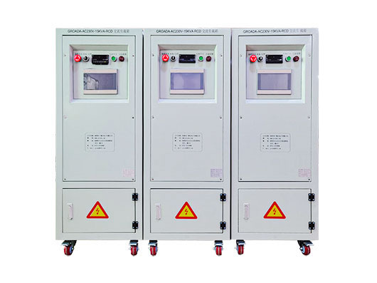
The GROADA AC Load Test Bench (AC230V, 15 kW, with Residual Current Device protection) is purpose-bu...
 04
04
GROADA-AC380V-30KW-RCD Inverter Load Box_Shenzhen Guang Lu Da Electronics Co., Ltd. is a high-tech e...