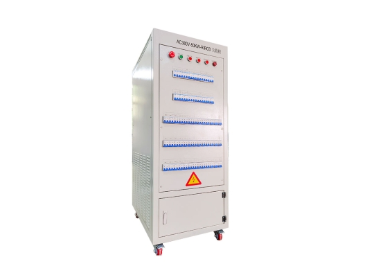
GROADA-AC380V-50KW-R/RCDインバータ負荷バンク
GROADA AC380V-50KW-R/RCDインバーターテストロードバンクは,高性能テストデバイス特定です...

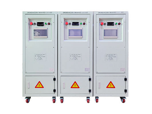
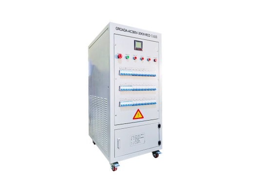
| モデル | AC220V-5KW-RCD | AC220V-10KW-RCD | AC220V-15KW-RCD | AC220V-20KW-RCD | AC380V の ・30KW-RCD | AC380V の ・50KW-RCD | AC380V の ・60KW-RCD | AC380V の ・100KW-RCD | AC380V の ・200KW-RCD |
| 評価パワー | R=5KW | R=10KW | R=15KW | R=20KW | R=30KW | R=50KW | R=60KW | R=100KW | R=200KW |
| RCD=5KVA | RCD=10KVA | RCD=15KVA | RCD=20KVA | RCD=30KVA | RCD=50KVA | RCD=60KVA | RCD=100KVA | RCD=200KVA | |
| 入力電流 | 0〜22A | 0〜45A | 0〜45A | 0-90A | 0〜45A | 0〜300A | 0-450A | 0〜600A | 0-750A |
| サイズ(幅*深さ*高さmm) | 500*600*800 | 500*600*1000 | 500*600*1100 | 500*750*1100 | 600*850*1400 | 600*850*1600 | 600*850*1850 | 700*1000*1800 | 1100*1400*1800 |
| 重量 | 50キログラム | 80キログラム | 100キログラム | 130キログラム | 200キログラム | 300キログラム | 350キログラム | 450キログラム | 550キログラム |
| 入力電圧 | AC220/230V | AC380/400V | |||||||
| 他の入力電圧は条件に従ってカスタマイズできます | |||||||||
| 最小負荷 | 100W | 100W | 100W | 100W | 100W | 1KW | 1KW | 1KW | 1KW |
| 他の最低負荷力は条件に従ってカスタマイズすることができます | |||||||||
| 全体的な精度 | 3%(他の正確さの条件は条件に従ってカスタマイズすることができます) | ||||||||
| パワーファクター | PF=0.6〜1.0 | ||||||||
| ピーク系数 | 2 から 3 | ||||||||
| 制御モード | ローカルマニュアル/リモートホストコンピュータ(ローカルマニュアル制御モード:ブレーカー/ボタン/タッチスクリーン三向任意、他の方法は必要に応じてカスタマイズすることができます) | ||||||||
| リモートインターフェース | RS232/RS485/USB/RJ45/CAN/GPIB(他のインターフェースモードは条件に応じてカスタマイズすることができます) | ||||||||
| 保護機能 | 緊急停止保護,過熱保護,ファン負荷インターロック保護,接地保護 (過電圧保護,過電流保護,短回路保護,ファン過負荷,空気量不足を選択) | ||||||||
| 働く電源 | AC220V の | AC220V/AC380V | |||||||
| 表示精度 | 0.5レベル(他の明確な精度は条件に従ってカスタマイズすることができます) | ||||||||
| 表示パラメータ | 電圧、電流、力、周波数、パワー要因等 (他の明示的な方法は条件に従ってカスタマイズすることができます) | ||||||||
| 冷たい確かな方法 | 側面の空気入口および上の空気出口(他の空気出口方法は条件に応じてカスタマイズすることができます) | ||||||||
| 保護レベル | IP20(他の保護レベルは条件に従ってカスタマイズすることができます) | ||||||||
| 外観色 | RAL7035(他の色は条件に従ってカスタマイズすることができます) | ||||||||
| 作業温度 | -10 ℃ ~ 55 ℃ | ||||||||
| 相対湿度 | ≤95%RH | ||||||||
| 高さ | ≤ 2500 m | ||||||||
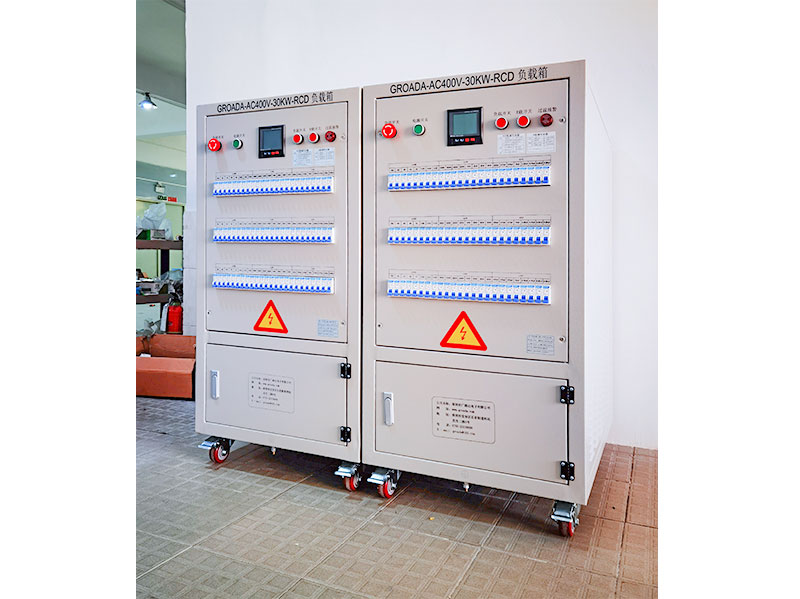
パワーエレクトロニクスや再生可能エネルギーシステムでは,インバータの性能の正確な検証が不可欠です. 「 TheAC 400 V/30 kW RCD インバータ負荷銀行インバータの検証,診断,および校正のための信頼性の高い,制御可能なテスト負荷を提供するように設計されています.この製品はR&ampで使用するために設計されています。D、品質管理、製造、およびフィールドサービス環境。
このページでは、技術的原則、テストユースケース、パフォーマンス仕様、および業界のベストプラクティスを説明します。
ロードバンクは,テスト中のインバータから制御された電流を引き出し,引き出された電力を熱 (または他の形態) に変換し,電圧,電流,電力,効率,動的行動の測定を可能にすることによって電気負荷をシミュレートします.簡単に言えば、制御された「ダミーロード」として機能し、インバータに圧力を与え、性能特性を明らかにします。
これは,発電機やUPSシステムで使用される標準的な負荷バンクに類似します.
インバータのテスト(特に光伏(PV)システム、モータードライブ、またはハイブリッドシステムの場合)では、ロードバンクがインバータが以下のことを確認するのに役立ちます。
完全負荷の下で評価された出力を維持する
一時的な負荷変更を処理する
波形の質、電圧&ampを維持します。周波数安定性
トリガー保護機能(過負荷、過電圧、過温)
長期間または気候ストレスの下で信頼性の高い動作
正確な負荷テストは,インバーターをフィールドに展開する前の重要なステップです. 安全性,信頼性,保証のためです.
インバータテストに使用される負荷シミュレーションは広く2つのカテゴリーがあります:
受動/抵抗負荷シンプルな抵抗負荷(純粹な抵抗)は直接で安定し、コスト効果的です。ベースラインパフォーマンステストに適しています。
アクティブ/反応/プログラム可能な負荷インダクタンス、容量、モーターのような行動、変化するパワー要因、一時的な行動、および双方向電流をエミュレートできるより高度な負荷。これらは現実的な条件(例えばモーター、グリッド相互作用)でインバータをテストする際に不可欠です。
例えば,プログラム可能なAC負荷 (アクティブAC負荷) は,そのインピーダンスを動的に変化させることができ,異なる負荷シナリオ (抵抗性,誘導性,混合性) でテストを可能にします.
負荷タイプの選択は,ターゲットアプリケーション (太陽光,電気自動車,モータードライブ) および必要なテストカバージョンによって異なります.
以下は,製品ページに適応したり,拡張したりできる仕様と機能コンテンツの構造を提案します.
| パラメータ | 典型的な値/範囲 | 重要性 / メモ |
|---|---|---|
| 名目出力電圧 | 380–480 V AC (or adjustable around 400 V) | Must match inverter output voltage to avoid mismatch |
| 評価パワー | 30 kW | Allows testing inverters up to this power class |
| Load control mode | Constant power / constant current / constant impedance | Versatility in various load profiles |
| Power factor range | 0.8 lag to 0.8 lead (or full range) | To emulate inductive or capacitive loads |
| Cooling method | Forced air / water-cooled | For thermal management under high load |
| Accuracy / measurement precision | e.g. ±0.5 % for current/voltage | Ensures accurate performance evaluation |
| Response time / dynamic bandwidth | e.g. <1 ms, or specified slew rate | Important for transient load changes |
| Protection & safety | Overload, overtemperature, overvoltage, short-circuit | Safeguards both load unit and inverter |
| Communication & control interfaces | RS-485, CAN, Ethernet, Modbus, SCPI | For remote control, automation, integration |
| Cooling / ambient support | Operation range (e.g. –20 °C to +60 °C) | Ensures performance under field-like conditions |
| Mechanical design | Compact modular racks, ease of integration | Facilitates adoption in test benches |
In your page, you can present these specifications clearly, with callouts (e.g. “Why this matters”), diagrams, and even downloadable PDF spec sheets.
You should also highlight unique selling points (USPs) such as:
Modular expansion (e.g. stacking load modules)
Fast dynamic response
High-precision measurement
Long-term durability (e.g. continuous full-load operation)
Safety certifications (CE, UL, etc.)
Ease of calibration and maintenance
These USPs help users compare your product against alternatives.
To strengthen E-E-A-T (especially Experience and Expertise), you should incorporate real-world use cases, test methodologies, and examples from industry. Below are four suggested scenarios:
In solar inverter R&D or production, load banks help validate output under varying irradiance, grid fluctuations, and load transients. You verify Maximum Power Point Tracking (MPPT) behavior, interaction with the grid (voltage/frequency synchronization).
You may simulate grid disturbances or ramp up/down loads to confirm inverter stability.
In electric vehicle or industrial motor drives, the inverter outputs to a motor. A load bank that can emulate motor behavior (inductive or dynamic load) is crucial, especially to test regenerative braking, transient response, or torque control. Active loads offer bi-directional current capability, enabling more realistic emulation.
You might also simulate load steps (rapid jerk in torque) and confirm that the inverter’s control loops recover properly.
To assess long-term reliability, the load bank is used to run continuous full-load or partial-load tests under temperature, humidity, vibration stress. Manufacturers like ATESTEO use climatic chambers to simulate environments from –60 °C to +160 °C during inverter testing.
Such tests help detect hidden defects (thermal drift, material fatigue, insulation issues) before field deployment.
In a production line environment, you may use the load bank to spot-check inverters, validate batch consistency, certify output under worst-case scenarios, or re-test returned units. The fast control interface allows automation and integration into manufacturing test benches.
Describing these concrete applications (with maybe anonymized client stories or case studies) strengthens credibility and usefulness of your page content.
To show experience and guide users, include a detailed “how-to” or best-practice section. This helps users trust your content as authoritative and actionable.
Preparation & Safety Checks
Confirm inverter is disengaged (no output)
Verify all safety interlocks
Check load bank calibration, cooling, cabling
Light Load / No-Load Baseline Test
Apply minimal resistive load (e.g. 5–10 % rating)
Check baseline behavior, waveform purity via oscilloscope
Verify no abnormal noise, heating, oscillation
Gradual Load Ramp-Up
Increase load in steps (e.g. 20 %, 50 %, 80 %, 100 %)
At each step, record voltage, current, real power, power factor, harmonic distortion
Monitor temperature, fan activity, internal protection thresholds
Full-Load Continuous Operation
Run for a designed dwell time (e.g. 1h, 4h, 8h)
Log any drift, dropouts, thermal stability
Confirm output remains within spec
Transient / Step-Change Tests
Suddenly change load (increase or decrease 20–50 %)
Observe response time, overshoot, oscillation
Verify inverter control stability
Overload & Fault Simulation (Optional)
Slightly exceed rated load to test protection
Induce fault (short) in controlled setup (if safety permits)
Confirm shutdown, alarm mechanisms
Cooling & Thermal Recovery Observation
After tests, allow cooldown
Monitor any residual heating or slow recovery
Data Analysis & Reporting
Compile results into charts (efficiency vs load, THD vs load, thermal profile)
Compare against design expectations, standards
You may reference general inverter testing guides (e.g. for pure sine wave inverters) as background.
Always derate load bank if ambient temperature is high
Ensure cable sizing to avoid voltage drop or overheating
Synchronize measurement devices (use proper instrumentation)
Periodically calibrate load modules to maintain accuracy
Use modular load bank design to scale capacity
Incorporate safety interlocks, ground references, emergency shutdown
Offering this detailed, stepwise methodology shows your team knows the domain—not just marketing fluff.
To add authority and context, you should reference broader market trends, statistics, or industry challenges. Below are suggestions you can expand:
The global inverter market (especially for solar, EV, and industrial drives) continues to grow at a robust CAGR, driving demand for reliable testing equipment (source: industry reports)
As inverters become more complex (multi-level topology, high switching frequency, integrated power electronics + control), the need for high-fidelity load banks (fast dynamic response, reactive load emulation) increases
In EV manufacturing, stringent qualification tests (e.g. ISO, automotive OEM standards) often mandate extended load testing under environmental stress
Renewable grid-interactive inverters must satisfy grid codes (anti-islanding, voltage/frequency ride-through), which means test systems must be able to emulate grid disturbances and loads
In many regions, warranty claims or field failures due to thermal stress or component drift can be mitigated by good pre-shipment load testing
You may want to cite recent market reports in your vertical to support such statements (e.g. “Solar inverter market size 2025–2030 forecasts” etc.).
Here you should deliver a persuasive, credibility-backed pitch, referencing your technical strengths and real-world validation:
Proven Reliability: Designed for continuous duty, with industrial-grade components, redundant cooling, and thermal protection.
High Precision & Diagnostics: Accurate metering, fine control steps, high-speed response for dynamic loads.
Modular & Scalable: Expandable modules allow you to satisfy 30 kW today, and scale to higher power in the future.
Integration & Automation: Full communication interfaces (Modbus, CAN, Ethernet) for linking to test benches, SCADA systems, or automated test sequences.
Safety & Compliance: Built according to major safety and quality standards; includes interlocks, alarms, protective features.
Support & Service: Backed by expert technical support, calibration services, and documentation.
You can further bolster this with customer testimonials, whitepapers, certification records, or case studies.
 01
01
GROADA AC380V-50KW-R/RCDインバーターテストロードバンクは,高性能テストデバイス特定です...
 02
02
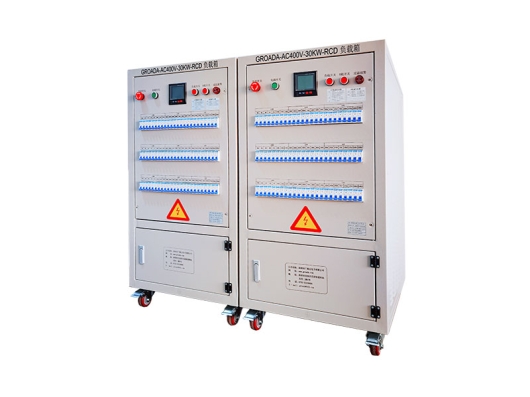
GROADA-AC400V-30KW-RCD インバータ AC 負荷_深圳市 Guangluda Electronics Co.、Ltd.はハイテク企業です。..
 03
03
GROADA AC負荷テストベンチ(AC230V、15 kW、残留電流装置保護付)は目的buです。..
 04
04
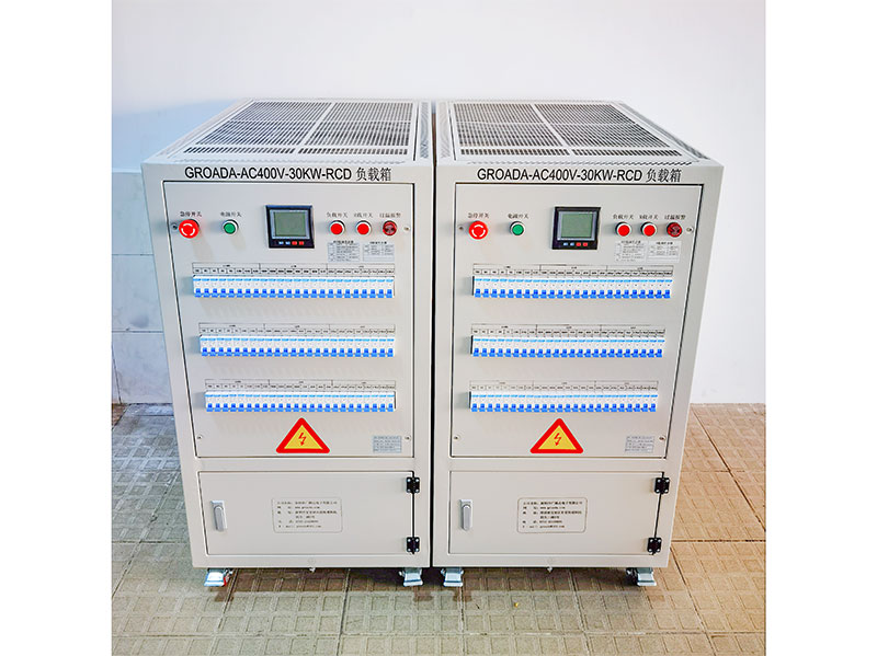
GROADA-AC380V-30KW-RCDインバータロードボックス_深セン市広ルダ電子株式会社はハイテク電子製品です...