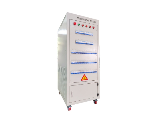
GROADA-AC380V-50KW-R/RCD 변환기 부하 은행
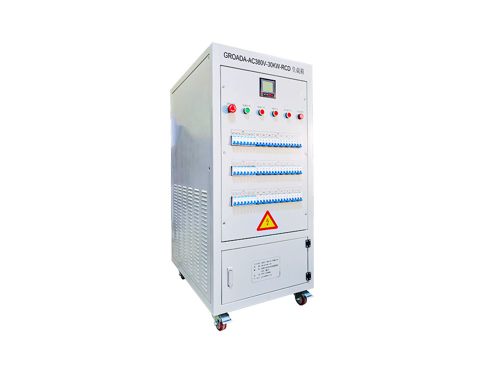
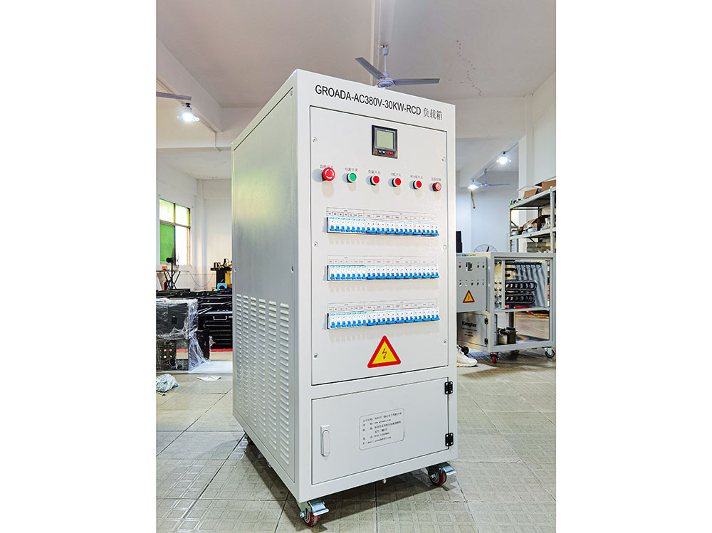
The GROADA AC380V-50KW-R/RCD inverter test load bank is a high-performance testing device specifical...
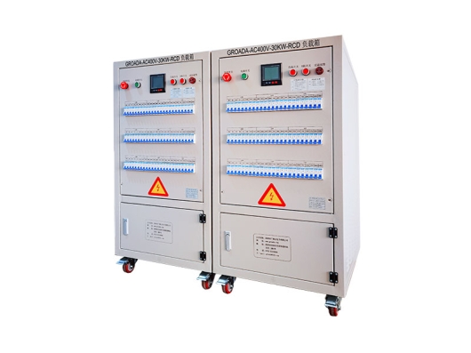
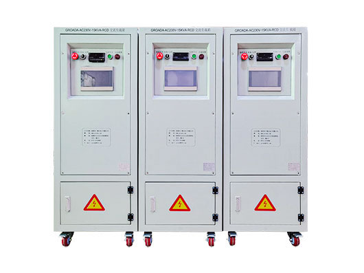
| 모델 | AC220V-5KW-RCD는 | AC220V-10KW-RCD는 | AC220V-15KW-RCD는 | AC220V-20KW-RCD는 | AC380V는 -30KW-RCD | AC380V는 -50KW-RCD | AC380V는 - 60KW-RCD | AC380V는 - 100KW-RCD | AC380V는 -200KW-RCD |
| 정격 전력 | R = 5KW | R = 10KW | R = 15KW | R = 20KW | R = 30KW | R = 50KW | R = 60KW | R = 100KW | R = 200KW |
| RCD = 5KVA | RCD = 10KVA | RCD = 15KVA | RCD = 20KVA | RCD = 30KVA | RCD = 50KVA | RCD = 60KVA | RCD = 100KVA | RCD = 200KVA | |
| 입력 현재 | 0-22A | 0-45A | 0-45A | 0-90A | 0-45A | 0-300A | 0-450A | 0-600A | 0-750A |
| 크기 (폭 * 깊이 * 높이 mm) | 500*600*800 | 500*600*1000 | 500*600*1100 | 500*750*1100 | 600*850*1400 | 600*850*1600 | 600*850*1850 | 700*1000*1800 | 1100*1400*1800 |
| 무게 | 50KG의 | 80KG의 | 100KG의 | 130KG의 | 200KG의 | 300KG의 | 350KG의 | 450KG의 | 550KG의 |
| 입력 전압 | AC220 / 230V | AC380/400V | |||||||
| 다른 입력 전압은 요구 사항에 따라 주문을 받아서 만들어질 수 있습니다 | |||||||||
| 최소 부하 | 100W | 100W | 100W | 100W | 100W | 1KW | 1KW | 1KW | 1KW |
| 다른 최소 적재 힘은 요구 사항에 따라 주문을 받아서 만들어질 수 있습니다 | |||||||||
| 전반적인 정확도 | 3% (다른 정확도 요구 사항은 요구 사항에 따라 주문을 받아서 만들어질 수 있습니다) | ||||||||
| 전력 요소 | PF = 0.6 ~ 1.0 | ||||||||
| 최고 계수 | 2에서 3까지 | ||||||||
| 제어 모드 | 지역 수동/원격 호스트 컴퓨터 (지역 수동 제어 모드: 차단기/버튼/터치 스크린 선택적 3 방향, 다른 방법은 필요에 따라 주문을 받아서 만들어질 수 있습니다) | ||||||||
| 원격 인터페이스 | RS232/RS485/USB/RJ45/CAN/GPIB (다른 인터페이스 형태는 요구 사항에 따라 주문을 받아서 만들어질 수 있습니다) | ||||||||
| 보호 기능 | 비상 정지 보호, 과온 보호, 팬 부하 인터로크 보호, 접지 보호 (과전압 보호, 과전류 보호, 단회로 보호, 팬 과부하, 부족한 공기 용량을 선택하십시오) | ||||||||
| 작동 전원 공급 | AC220V는 | AC220V / AC380V | |||||||
| 표시 정확도 | 0.5 수준 (다른 명시적인 정밀도는 요구 사항에 따라 주문을 받아서 만들어질 수 있습니다) | ||||||||
| 표시 매개 변수 | 전압, 전류, 힘, 주파수, 전력 요인 등. (다른 명시적인 방법은 요구 사항에 따라 주문을 받아서 만들어질 수 있습니다) | ||||||||
| 차가운 확실한 방법 | 측면 공기 입구 및 위 공기 출구 (다른 공기 출구 방법은 요구 사항에 따라 주문을 받아서 만들어질 수 있습니다) | ||||||||
| 보호 수준 | IP20 (다른 보호 수준은 요구 사항에 따라 주문을 받아서 만들어질 수 있습니다) | ||||||||
| 외관 색깔 | RAL7035 (다른 색깔은 요구 사항에 따라 주문을 받아서 만들어질 수 있습니다) | ||||||||
| 작동 온도 | -10 ℃ ~ 55 ℃ | ||||||||
| 상대 습도 | ≤95%RH | ||||||||
| 고도 | ≤ 2500 m | ||||||||
현실적이고 통제가능한 부하에서 인버터 테스트는 성능, 신뢰성, 내구성 및 안전성을 확인하는 데 필수적입니다.적절하게 설계된 로드 적용은행은 다음을 허용합니다.
전체 부하, 부부하 및 일시적인 조건에서 재생 가능한 스트레스 테스트
실제 모터 또는 그리드 상호 작용을 시뮬레이션하는 저항, 유도 또는 결합 부하 제어
보호 회로의 검증 (과전류, 과전압, 열 종료)
장기 열 안정성, 노화 및 구성 요소 분해 확인
그러한 로드 그러한 부하 은행이 없으면 인버터 테스트는 현장 조건이나 모터 커플링에만 의존할 수 있으며, 이는 근본 원인 분석을 모호화하고 반복성을 줄일 수 있습니다.
사실, 산업 표준 테스트 실험실은 수동 (저항 / 유도) 및 활성 부하 (재생 전자 부하 또는 모터 에뮬레이터) 모두 완전히 스트레스 인버터를 사용합니다.
이 제품 페이지는 AC 380 V 시스템을 위해 특별히 설계된 고정밀 인버터 로드 이 최대 30 kW 정격 로드를 처리할 수 있는 고정밀 인버터 로드 이 이 이 이 제시됩니다.아래는 향상된 SEO 최적화된 설명입니다:
명목적 전압:380 V AC
정격 힘:30 kW 연속
부하 유형:RCD (저항 + 용량 + 유도 조합)
부하 제어 형태:단계별 또는 지속적인 조정, 부분적 부하 (예: 10 %, 25 %, 50 %, 75 %, 100 %)
냉각 &열 관리:강제 공기 또는 액체 냉각 전체 부하 하에서 안정적인 온도를 유지하기 위해
Protection Mechanisms: overcurrent, overvoltage, short-circuit, phase loss, overheating
Load Bank Construction: high-stability precision resistors/inductors, modular load elements
Measurement & Monitoring: integrated current, voltage, power, and temperature sensors; optional logging or remote communication
These features empower R&D labs, quality assurance teams, and inverter manufacturers to test inverters precisely under controlled, repeatable load conditions.
During the design and prototyping phases, engineers can use this load bank to:
Verify full-load performance, thermal limits, and efficiency curves
Stress-test inverter switching components (IGBTs, MOSFETs)
Simulate part-load, transient, and overload scenarios
Validate cooling systems under real thermal load
In mass manufacturing, this load bank can be integrated into automatic test sequences:
Run “burn-in” or "soak" tests to detect early-life failures
Ensure each unit meets declared performance before shipping
Automate pass/fail criteria based on voltage, current, power, and temperature thresholds
After deployment (in solar farms, microgrids, industrial power systems), periodic or after-maintenance tests help:
Confirm the inverter still performs within specification
Detect degradation (e.g. diminished cooling, capacitor aging)
Validate protection circuits and safety margins
Testing inverters with a load bank is considered a best practice in many critical power installations to prevent unexpected failure.
Below is a recommended step-by-step workflow and key considerations:
| Phase | Actions | Purpose / Checks |
|---|---|---|
| Setup & Safety Check | Inspect wiring, ensure insulation and grounding, perform open-circuit checks | Prevent shorts or unsafe conditions |
| No-load / Idle Measurement | Run inverter unloaded, measure baseline current, voltage, harmonic distortion | Confirm zero-load behavior and idle losses |
| Step Load Ramp | Apply incremental loads (e.g. 10 %, 25 %, 50 %, 75 %, 100 %) | Assess linearity, thermal drift, current stability |
| Full-load Endurance / Soak Test | Run at full load for extended duration (hours to days) | Monitor temperature, drift, cooling effectiveness |
| Transient Tests | Introduce load steps, sudden load removal (load rejection), or overload transients | Measure inverter’s dynamic response, grid-interaction behavior |
| Protection Verification | Deliberately exceed ratings to trigger overcurrent, overvoltage, or thermal protections | Validate that safety circuits engage reliably |
Always wear proper PPE (insulating gloves, goggles) when handling high-voltage systems.
Ensure the load bank and inverter are in good ventilation and clean environment (no dust accumulation).
Use power meters or precision instrumentation to measure input/output, so your efficiency calculations are accurate.
Avoid exceeding design limits of the inverter or load bank – inconsistent or overloaded operation can damage components.
Record all data logs systematically for traceability and future analysis.
To support EEAT and improve trust, you may wish to include:
Testing data and charts (efficiency curve, thermal profiles)
Third-party lab certifications (e.g. IEC, UL, CE compliance)
Case studies or whitepapers where this or similar load banks have been used (e.g. in inverter manufacturers’ labs)
Technical team credentials (engineers, years in power electronics, publications)
Guarantees and warranty terms, e.g. accuracy drift, calibration support
Our AC 380V 30 kW RCD Inverter Load Bank is engineered by a team with over 10 years of experience in power electronics test systems. Designed for R&D, QA, and maintenance verification, it meets international accuracy and safety standards. Each unit is factory-calibrated and accompanied by a calibration certificate. We also offer custom configurations (higher power, alternate voltages, communication interfaces) to support evolving test requirements.
 01
01
The GROADA AC380V-50KW-R/RCD inverter test load bank is a high-performance testing device specifical...
 02
02
GROADA-AC400V-30KW-RCD Inverter AC Load_Shenzhen Guangluda Electronics Co., Ltd. is a high-tech ente...
 03
03
The GROADA AC Load Test Bench (AC230V, 15 kW, with Residual Current Device protection) is purpose-bu...
 04
04
GROADA-AC380V-30KW-RCD Inverter Load Box_Shenzhen Guang Lu Da Electronics Co., Ltd. is a high-tech e...