GROADA-AC380V-50KW-R/RCD 변환기 부하 은행
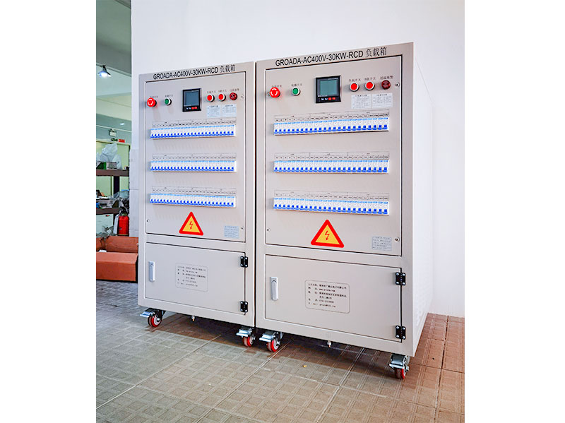
The GROADA AC380V-50KW-R/RCD inverter test load bank is a high-performance testing device specifical...

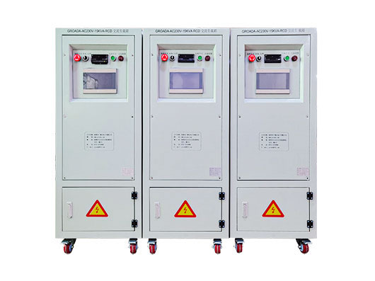
| 모델 | AC220V-5KW-RCD는 | AC220V-10KW-RCD는 | AC220V-15KW-RCD는 | AC220V-20KW-RCD는 | AC380V는 -30KW-RCD | AC380V는 -50KW-RCD | AC380V는 - 60KW-RCD | AC380V는 - 100KW-RCD | AC380V는 -200KW-RCD |
| 정격 전력 | R = 5KW | R = 10KW | R = 15KW | R = 20KW | R = 30KW | R = 50KW | R = 60KW | R = 100KW | R = 200KW |
| RCD = 5KVA | RCD = 10KVA | RCD = 15KVA | RCD = 20KVA | RCD = 30KVA | RCD = 50KVA | RCD = 60KVA | RCD = 100KVA | RCD = 200KVA | |
| 입력 현재 | 0-22A | 0-45A | 0-45A | 0-90A | 0-45A | 0-300A | 0-450A | 0-600A | 0-750A |
| 크기 (폭 * 깊이 * 높이 mm) | 500*600*800 | 500*600*1000 | 500*600*1100 | 500*750*1100 | 600*850*1400 | 600*850*1600 | 600*850*1850 | 700*1000*1800 | 1100*1400*1800 |
| 무게 | 50KG의 | 80KG의 | 100KG의 | 130KG의 | 200KG의 | 300KG의 | 350KG의 | 450KG의 | 550KG의 |
| 입력 전압 | AC220 / 230V | AC380/400V | |||||||
| 다른 입력 전압은 요구 사항에 따라 주문을 받아서 만들어질 수 있습니다 | |||||||||
| 최소 부하 | 100W | 100W | 100W | 100W | 100W | 1KW | 1KW | 1KW | 1KW |
| 다른 최소 적재 힘은 요구 사항에 따라 주문을 받아서 만들어질 수 있습니다 | |||||||||
| 전반적인 정확도 | 3% (다른 정확도 요구 사항은 요구 사항에 따라 주문을 받아서 만들어질 수 있습니다) | ||||||||
| 전력 요소 | PF = 0.6 ~ 1.0 | ||||||||
| 최고 계수 | 2에서 3까지 | ||||||||
| 제어 모드 | 지역 수동/원격 호스트 컴퓨터 (지역 수동 제어 모드: 차단기/버튼/터치 스크린 선택적 3 방향, 다른 방법은 필요에 따라 주문을 받아서 만들어질 수 있습니다) | ||||||||
| 원격 인터페이스 | RS232/RS485/USB/RJ45/CAN/GPIB (다른 인터페이스 형태는 요구 사항에 따라 주문을 받아서 만들어질 수 있습니다) | ||||||||
| 보호 기능 | 비상 정지 보호, 과온 보호, 팬 부하 인터로크 보호, 접지 보호 (과전압 보호, 과전류 보호, 단회로 보호, 팬 과부하, 부족한 공기 용량을 선택하십시오) | ||||||||
| 작동 전원 공급 | AC220V는 | AC220V / AC380V | |||||||
| 표시 정확도 | 0.5 수준 (다른 명시적인 정밀도는 요구 사항에 따라 주문을 받아서 만들어질 수 있습니다) | ||||||||
| 표시 매개 변수 | 전압, 전류, 힘, 주파수, 전력 요인 등. (다른 명시적인 방법은 요구 사항에 따라 주문을 받아서 만들어질 수 있습니다) | ||||||||
| 차가운 확실한 방법 | 측면 공기 입구 및 위 공기 출구 (다른 공기 출구 방법은 요구 사항에 따라 주문을 받아서 만들어질 수 있습니다) | ||||||||
| 보호 수준 | IP20 (다른 보호 수준은 요구 사항에 따라 주문을 받아서 만들어질 수 있습니다) | ||||||||
| 외관 색깔 | RAL7035 (다른 색깔은 요구 사항에 따라 주문을 받아서 만들어질 수 있습니다) | ||||||||
| 작동 온도 | -10 ℃ ~ 55 ℃ | ||||||||
| 상대 습도 | ≤95%RH | ||||||||
| 고도 | ≤ 2500 m | ||||||||
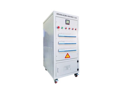
전력 전자 제품과 재생 가능 에너지 시스템에서 인버터 성능의 정확한 검증은 필수적입니다.TheAC 400 V/30 kW RCD 변환기 부하 은행인버터 검증, 진단 및 캘리브레이션을 위한 신뢰할 수 있고 통제할 수 있는 시험 부하를 제공하기 위해 설계되었습니다.이 제품은 R&에서 사용하기 위해 설계되었습니다.D, 품질 관리, 제조 및 현장 서비스 환경.
이 페이지는 기술 원칙, 테스트 사용 사례, 성능 사양 및 산업 모범 사례를 설명하여 엔지니어, 프로젝트 리드 및 의사 결정자가 정보를 갖춘 선택을 할 수 있도록 도와줍니다.
로드 로드 로로드 로로로드 로로로드 로로로드 로로로드 로로로드 로로로드 로드 로로로드 로드 로로로드 로로로로드 로로로로드 로로로로로드 로로드 로드 로드 로로드 로드 로드 로드 로드에서 제된 전류된 전류된 전류 전간단히 말해서: 그것은 인버터를 스트레스하고 성능 특성을 드러내기 위해 통제되는 "더미 로드"로 작동합니다.
이것은 발전기 또는 UPS 시스템에 사용되는 표준 부하 은행과 비슷합니다.
In inverter testing (especially for photovoltaic (PV) systems, motor drives, or hybrid systems), a load bank helps confirm that the inverter can:
Sustain rated output under full load
Handle transient load changes
Maintain waveform quality, voltage & frequency stability
Trigger protective functions (overload, overvoltage, overtemperature)
Operate reliably over extended duration or under climatic stress
Accurate load testing is a key step before deploying inverters to the field — for safety, reliability, and warranty assurance.
There are broadly two categories of load simulation used in inverter testing:
Passive / Resistive Loads — simple resistive loads (pure resistance) are straightforward, stable, and cost-effective. They are good for baseline performance tests.
Active / Reactive / Programmable Loads — more advanced loads that can emulate inductance, capacitance, motor-like behavior, varying power factor, transient behaviors, and bi-directional current flow. These are essential when testing inverters under realistic conditions (e.g. with motors, grid interactions).
For example, a programmable AC load (active AC load) can vary its impedance dynamically, enabling tests across different load scenarios (resistive, inductive, mixed).
The choice of load type depends on the target application (solar, electric vehicle, motor drive) and required test coverage.
Below is a suggested structure of specification and feature content you can adapt or extend for your product page.
| 매개 변수 | Typical Value / Range | Importance / Notes |
|---|---|---|
| Nominal output voltage | 380–480 V AC (or adjustable around 400 V) | Must match inverter output voltage to avoid mismatch |
| 정격 전력 | 30 kW | Allows testing inverters up to this power class |
| Load control mode | Constant power / constant current / constant impedance | Versatility in various load profiles |
| Power factor range | 0.8 lag to 0.8 lead (or full range) | To emulate inductive or capacitive loads |
| Cooling method | Forced air / water-cooled | For thermal management under high load |
| Accuracy / measurement precision | e.g. ±0.5 % for current/voltage | Ensures accurate performance evaluation |
| Response time / dynamic bandwidth | e.g. <1 ms, or specified slew rate | Important for transient load changes |
| Protection & safety | Overload, overtemperature, overvoltage, short-circuit | Safeguards both load unit and inverter |
| Communication & control interfaces | RS-485, CAN, Ethernet, Modbus, SCPI | For remote control, automation, integration |
| Cooling / ambient support | Operation range (e.g. –20 °C to +60 °C) | Ensures performance under field-like conditions |
| Mechanical design | Compact modular racks, ease of integration | Facilitates adoption in test benches |
In your page, you can present these specifications clearly, with callouts (e.g. “Why this matters”), diagrams, and even downloadable PDF spec sheets.
You should also highlight unique selling points (USPs) such as:
Modular expansion (e.g. stacking load modules)
Fast dynamic response
High-precision measurement
Long-term durability (e.g. continuous full-load operation)
Safety certifications (CE, UL, etc.)
Ease of calibration and maintenance
These USPs help users compare your product against alternatives.
To strengthen E-E-A-T (especially Experience and Expertise), you should incorporate real-world use cases, test methodologies, and examples from industry. Below are four suggested scenarios:
In solar inverter R&D or production, load banks help validate output under varying irradiance, grid fluctuations, and load transients. You verify Maximum Power Point Tracking (MPPT) behavior, interaction with the grid (voltage/frequency synchronization).
You may simulate grid disturbances or ramp up/down loads to confirm inverter stability.
In electric vehicle or industrial motor drives, the inverter outputs to a motor. A load bank that can emulate motor behavior (inductive or dynamic load) is crucial, especially to test regenerative braking, transient response, or torque control. Active loads offer bi-directional current capability, enabling more realistic emulation.
You might also simulate load steps (rapid jerk in torque) and confirm that the inverter’s control loops recover properly.
To assess long-term reliability, the load bank is used to run continuous full-load or partial-load tests under temperature, humidity, vibration stress. Manufacturers like ATESTEO use climatic chambers to simulate environments from –60 °C to +160 °C during inverter testing.
Such tests help detect hidden defects (thermal drift, material fatigue, insulation issues) before field deployment.
In a production line environment, you may use the load bank to spot-check inverters, validate batch consistency, certify output under worst-case scenarios, or re-test returned units. The fast control interface allows automation and integration into manufacturing test benches.
Describing these concrete applications (with maybe anonymized client stories or case studies) strengthens credibility and usefulness of your page content.
To show experience and guide users, include a detailed “how-to” or best-practice section. This helps users trust your content as authoritative and actionable.
Preparation & Safety Checks
Confirm inverter is disengaged (no output)
Verify all safety interlocks
Check load bank calibration, cooling, cabling
Light Load / No-Load Baseline Test
Apply minimal resistive load (e.g. 5–10 % rating)
Check baseline behavior, waveform purity via oscilloscope
Verify no abnormal noise, heating, oscillation
Gradual Load Ramp-Up
Increase load in steps (e.g. 20 %, 50 %, 80 %, 100 %)
At each step, record voltage, current, real power, power factor, harmonic distortion
Monitor temperature, fan activity, internal protection thresholds
Full-Load Continuous Operation
Run for a designed dwell time (e.g. 1h, 4h, 8h)
Log any drift, dropouts, thermal stability
Confirm output remains within spec
Transient / Step-Change Tests
Suddenly change load (increase or decrease 20–50 %)
Observe response time, overshoot, oscillation
Verify inverter control stability
Overload & Fault Simulation (Optional)
Slightly exceed rated load to test protection
Induce fault (short) in controlled setup (if safety permits)
Confirm shutdown, alarm mechanisms
Cooling & Thermal Recovery Observation
After tests, allow cooldown
Monitor any residual heating or slow recovery
Data Analysis & Reporting
Compile results into charts (efficiency vs load, THD vs load, thermal profile)
Compare against design expectations, standards
You may reference general inverter testing guides (e.g. for pure sine wave inverters) as background.
Always derate load bank if ambient temperature is high
Ensure cable sizing to avoid voltage drop or overheating
Synchronize measurement devices (use proper instrumentation)
Periodically calibrate load modules to maintain accuracy
Use modular load bank design to scale capacity
Incorporate safety interlocks, ground references, emergency shutdown
Offering this detailed, stepwise methodology shows your team knows the domain—not just marketing fluff.
To add authority and context, you should reference broader market trends, statistics, or industry challenges. Below are suggestions you can expand:
The global inverter market (especially for solar, EV, and industrial drives) continues to grow at a robust CAGR, driving demand for reliable testing equipment (source: industry reports)
As inverters become more complex (multi-level topology, high switching frequency, integrated power electronics + control), the need for high-fidelity load banks (fast dynamic response, reactive load emulation) increases
In EV manufacturing, stringent qualification tests (e.g. ISO, automotive OEM standards) often mandate extended load testing under environmental stress
Renewable grid-interactive inverters must satisfy grid codes (anti-islanding, voltage/frequency ride-through), which means test systems must be able to emulate grid disturbances and loads
In many regions, warranty claims or field failures due to thermal stress or component drift can be mitigated by good pre-shipment load testing
You may want to cite recent market reports in your vertical to support such statements (e.g. “Solar inverter market size 2025–2030 forecasts” etc.).
Here you should deliver a persuasive, credibility-backed pitch, referencing your technical strengths and real-world validation:
Proven Reliability: Designed for continuous duty, with industrial-grade components, redundant cooling, and thermal protection.
High Precision & Diagnostics: Accurate metering, fine control steps, high-speed response for dynamic loads.
Modular & Scalable: Expandable modules allow you to satisfy 30 kW today, and scale to higher power in the future.
Integration & Automation: Full communication interfaces (Modbus, CAN, Ethernet) for linking to test benches, SCADA systems, or automated test sequences.
Safety & Compliance: Built according to major safety and quality standards; includes interlocks, alarms, protective features.
Support & Service: Backed by expert technical support, calibration services, and documentation.
You can further bolster this with customer testimonials, whitepapers, certification records, or case studies.
 01
01
The GROADA AC380V-50KW-R/RCD inverter test load bank is a high-performance testing device specifical...
 02
02
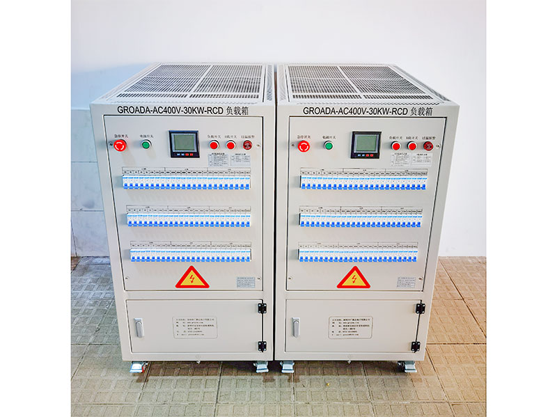
GROADA-AC400V-30KW-RCD Inverter AC Load_Shenzhen Guangluda Electronics Co., Ltd. is a high-tech ente...
 03
03
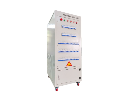
The GROADA AC Load Test Bench (AC230V, 15 kW, with Residual Current Device protection) is purpose-bu...
 04
04
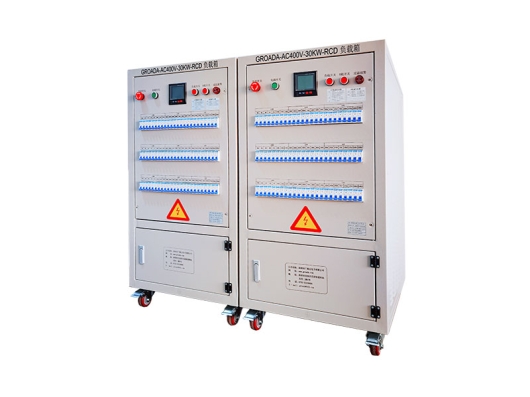
GROADA-AC380V-30KW-RCD Inverter Load Box_Shenzhen Guang Lu Da Electronics Co., Ltd. is a high-tech e...