Portable Load Bank Testing for Generator and UPS Systems
Load bank testing is a critical process in ensuring the reliability, performance, and safety of power generation and backup systems such as diesel generators, gas turbines, and uninterruptible power supplies (UPS). A portable load bank allows engineers to simulate real-world electrical loads on these systems without requiring actual consumption of energy from the grid or facility. This method enables comprehensive diagnostics, validation of system capacity, and identification of potential failures before they occur in live operation.
There are three primary types of load banks: resistive, reactive, and combination (RLC). Resistive load banks simulate purely resistive loads like lighting, heating elements, and motor drives, making them ideal for basic generator testing. Reactive load banks, which can be inductive or capacitive, emulate motors, transformers, and other inductive or capacitive devices—important for evaluating voltage regulation, excitation system response, and power factor behavior. Combination load banks offer both resistive and reactive components in adjustable ratios, allowing full-system simulation for complex applications such as data centers, hospitals, and industrial plants.
The design of modern portable load banks integrates robust thermal management, remote monitoring capabilities, and compliance with international standards like IEC 60034-1 for electric machine testing and IEEE 1159 for power quality. These standards influence everything from insulation resistance requirements to harmonic distortion limits during testing. For instance, IEC 60034-1 mandates that machines undergo load tests at rated current and voltage conditions to verify mechanical integrity and temperature rise characteristics. Similarly, IEEE 1159 specifies permissible levels of voltage sags, flicker, and harmonics, guiding how load banks must mimic real-world disturbances when used in commissioning scenarios.
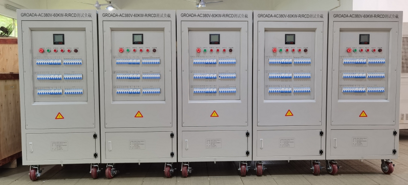
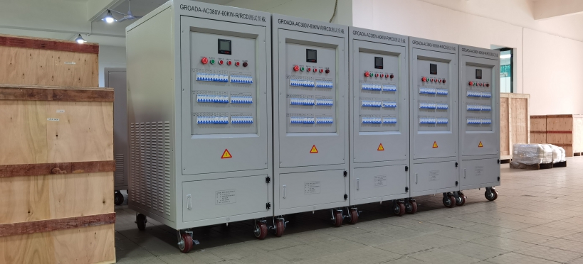
Portable load banks typically range from 5 kW to over 2,000 kVA depending on application needs. Single-phase units are common for small commercial buildings or residential backup systems, while three-phase models dominate industrial and utility-scale deployments. Key parameters include maximum current handling (often 50–500 A per phase), adjustable power factor (from 0.8 lagging to 1.0 leading), and precision measurement accuracy within ±0.5% for active and reactive power. Advanced models feature digital controls via Modbus RTU or Ethernet, enabling automated load ramping, data logging, and integration into SCADA systems.
Thermal protection is essential; many units incorporate air-cooled resistor blocks with forced ventilation using high-efficiency fans. Some heavy-duty models use water-cooling for continuous operation under high-load conditions. Temperature sensors monitor internal hotspots, triggering automatic shutdown if thresholds exceed 150°C—a safety measure aligned with UL 1004 guidelines for electrical equipment. Overvoltage and undervoltage protections prevent damage to sensitive electronics, while short-circuit protection ensures circuit breakers trip rapidly in fault events.
Mechanical construction focuses on portability and durability. Units are housed in rugged steel enclosures with IP54 ratings to withstand dust and splashing water—common in field environments. Forklift pockets, lifting eyes, and casters facilitate easy transport between sites. Weight varies from 50 kg for benchtop units to over 2,000 kg for large mobile setups, emphasizing the need for proper handling procedures and trained personnel.
Maintenance involves regular calibration every 12 months using certified reference standards such as those provided by NIST (National Institute of Standards and Technology). Consumables like resistor blocks may require replacement after 5–10 years based on usage intensity. Fans, cooling filters, and contactors should be inspected quarterly. A recommended spare parts list includes fuse holders, thermocouples, control boards, and connector kits for quick repair cycles.
Case Study 1 – Factory Acceptance Test (FAT) for a 1 MW Diesel Generator
In an anonymized case study involving a manufacturing plant in Germany, a portable RLC load bank was used to conduct FAT on a new 1 MW diesel generator. The test included 100%, 75%, and 50% load steps over 2 hours each, with power factor adjusted from 0.8 lagging to unity. Voltage regulation remained within ±2% across all stages, confirming stable excitation control. No overheating occurred, and emissions met EU Stage IIIA regulations. Based on this test, the customer accepted the unit confidently, avoiding costly delays post-installation.
Case Study 2 – Data Center UPS Validation
At a Tier III data center in Singapore, a 500 kVA resistive load bank tested the UPS system’s ability to handle sudden load changes. During a simulated blackout scenario, the UPS transferred seamlessly from utility to battery mode in less than 10 ms. Load bank readings confirmed that output voltage stayed within 110–120 VAC (±1%) throughout the transition, validating system resilience. Post-test analysis revealed minor inefficiencies in inverter efficiency at partial loads—addressed through firmware updates.
These examples illustrate how portable load banks provide actionable insights beyond simple functionality checks—they reveal hidden inefficiencies, validate emergency protocols, and support predictive maintenance strategies. In today’s increasingly complex power infrastructures, especially with renewable integration and microgrid developments, portable load testing has become indispensable for operators seeking operational excellence and regulatory compliance.