Automatic Load Bank Wiring Diagram Explained for Efficient Electrical Testing
An automatic load bank wiring diagram is a critical tool for engineers and technicians involved in generator testing, power system validation, and electrical infrastructure commissioning. Unlike manual setups, an automated system ensures precise, repeatable loading of electrical sources—such as diesel generators or UPS systems—while minimizing human error and enhancing safety. This wiring diagram outlines how resistive, reactive, or combined RLC (resistance-inductance-capacitance) loads are connected to the test source using contactors, control relays, and digital monitoring units.
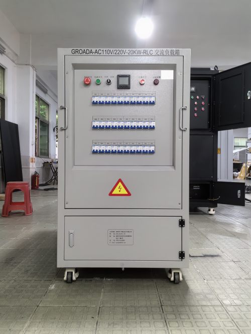
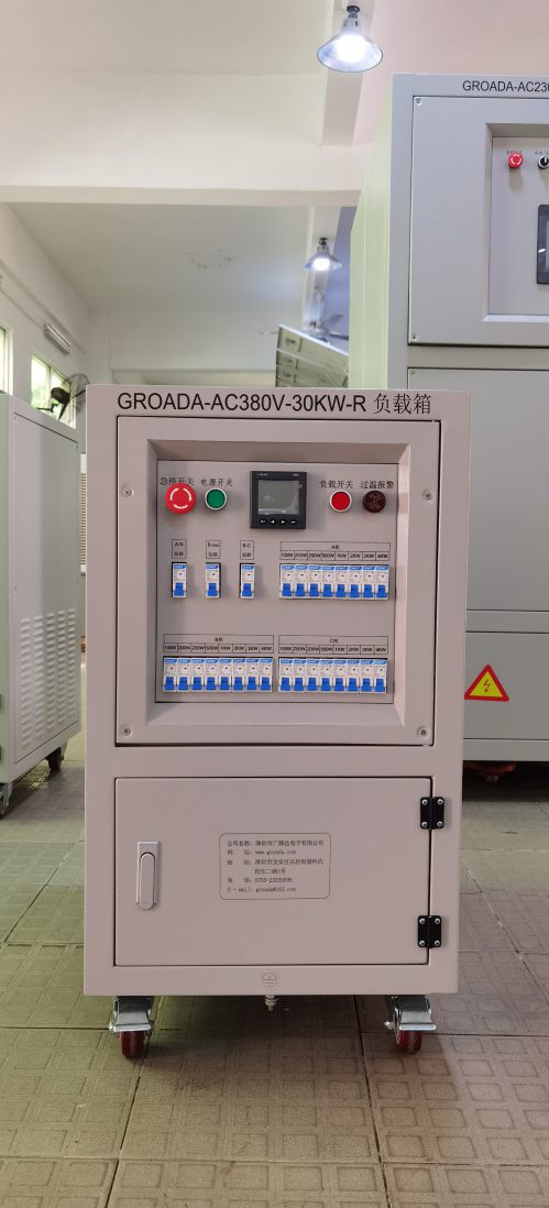
The core components typically include a programmable controller (often with Modbus or Ethernet interfaces), a bank of precision resistor blocks, inductive or capacitive modules for power factor adjustment, and temperature sensors integrated into each load module. For three-phase applications, the wiring must ensure balanced loading across all phases, often verified through real-time voltage and current measurements. In factory acceptance tests (FAT), this setup allows for stepwise load application—such as 25%, 50%, 75%, and 100% of rated capacity—to simulate real-world conditions.
Modern systems also incorporate remote monitoring capabilities, enabling operators to adjust load levels via software or mobile apps. Safety features like overtemperature protection, emergency stop circuits, and ground fault detection are wired directly into the control logic. According to IEC 60034-1, such standardized load testing procedures help validate motor performance and generator output under varying load conditions, ensuring reliability before deployment.
Whether used in wind farm grid integration testing or data center backup power verification, understanding the automatic load bank wiring diagram is essential for accurate, efficient, and safe electrical load testing. Engineers can use these diagrams to troubleshoot issues quickly, reduce downtime, and optimize system performance during both commissioning and maintenance phases.