Delta Load Bank Image Explained for Electrical Testing Professionals
A delta load bank image is a critical visual reference used in the testing and validation of electrical power systems, especially when evaluating generator sets, uninterruptible power supplies (UPS), and renewable energy inverters. Unlike standard star (wye) configurations, the delta connection allows for balanced three-phase load distribution with higher fault current capability—making it ideal for high-power industrial applications such as data centers, hospitals, and manufacturing plants.
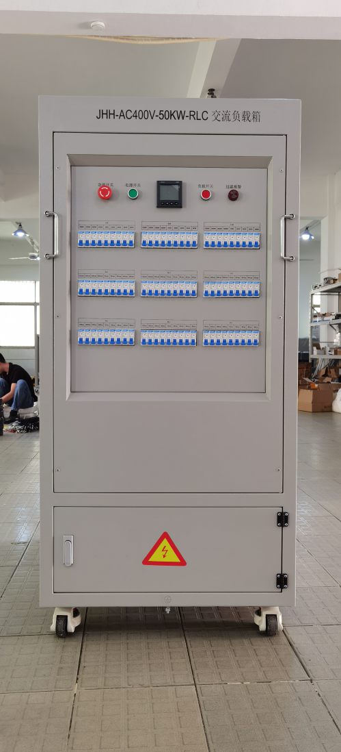
The image typically shows how resistive or reactive loads are connected across the three phases using a delta topology, where each load element links between two phase lines rather than from phase to neutral. This configuration is common in portable and static load banks used during factory acceptance tests (FATs), commissioning, and preventive maintenance. Engineers rely on these diagrams to verify correct wiring, avoid phase imbalance, and ensure safety compliance per IEC 60034-1 and IEEE 1159 standards.
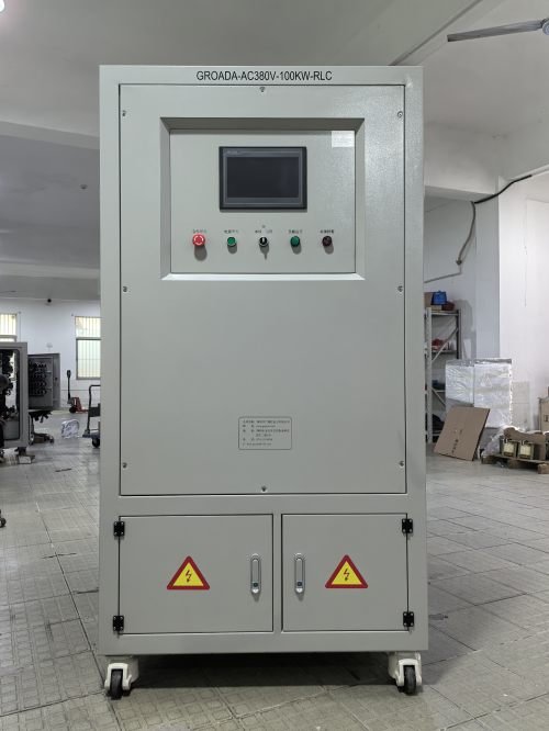
Modern digital load banks often include built-in monitoring systems that display real-time load profiles, power factor, and temperature rise—all essential metrics for verifying system performance under stress. In practice, a delta load bank image may also show thermal protection circuits, grounding points, and control interfaces like Modbus RTU or Ethernet for remote diagnostics. These visuals help technicians interpret load behavior during step-wise loading tests, simulate grid faults, or validate voltage regulation in microgrid setups.
For example, in an anonymized case study involving a 1 MW diesel generator, engineers used a delta-connected resistive load bank to test full-load performance over 8 hours. The delta configuration allowed consistent load sharing across all phases, preventing overheating issues seen in earlier wye-based setups. Measurements confirmed a stable power factor within ±0.02 range, validating the generator’s ability to handle peak demand without voltage sag.
Understanding delta load bank images enhances troubleshooting accuracy, improves test repeatability, and supports compliance with international safety regulations such as UL 1008 and CE marking requirements. Whether you're conducting dynamometer testing, performing routine UPS load tests, or preparing for grid interconnection certification, this visual tool remains indispensable.